Tesla Model S: Module - Air Suspension - ECU (Remove and Replace)
Warning: If the 12V power supply is disconnected, do not attempt to open any doors with door glass in closed position. Failure to follow this instruction could result in door glass shatter.
Note: Before disconnecting the 12V power supply, ensure that the driver's door window is fully open. Failure to follow this instruction could result in vehicle lockout.
Removal
- Move the driver seat to its rearward most position.
- Disconnect 12V power.
- Rear wheel drive (RWD): Refer to procedure.
- Dual Motor: Refer to procedure.
- Remove the center console assembly (refer to procedure).
- Carefully peel back the carpet for access. Caution: Take care not to damage component(s).
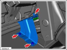
- Remove the bolts (x3) that secure the air suspension mounting
bracket to the body (torque metal bracket 8 Nm; plastic bracket 2
Nm).
Note: The horizontal bolt might be obscured by an acoustic pad. If it is, carefully move the acoustic pad aside for access.
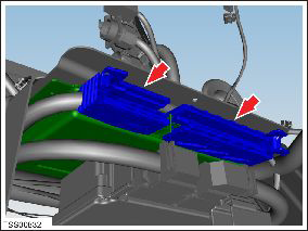
- Gently lift up on the bracket and disconnect the harnesses
connectors (x2) at the rear of the ECU.
- Carefully remove the ECU and bracket assembly from the dash assembly.
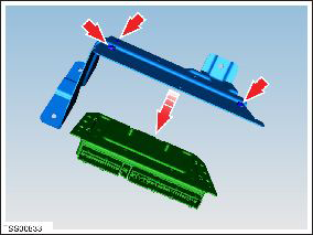
- Release the bolts (x3) that secure the bracket to the ECU.
Remove the ECU from the bracket
Installation procedure is the reverse of removal, except for the following:
- Run the Toolbox "Air Suspension Variant Coding" procedure.
-
Use Toolbox to update or redeploy the firmware:
- If the vehicle is not running the latest firmware, run the "Vehicle Firmware Update" procedure.
- If the vehicle is running the latest firmware, run the "Firmware Redeploy" procedure.
- Perform a ride height calibration (refer to procedure).
READ NEXT:
 Module - Air Suspension - ECU (Remove and Install)
Warning: If the 12V power supply is disconnected, do
not attempt to open any doors with door glass in closed position.
Failure to follow this instruction could result in door glass
shat
Module - Air Suspension - ECU (RHD) (Remove and Replace)
Warning: If the 12V power supply is disconnected, do
not attempt to open any doors with door glass in closed position.
Failure to follow this instruction could result in door glass
shat
Module - Air Suspension - ECU (RHD) (Remove and Install)
Warning: If the 12V power supply is disconnected, do
not attempt to open any doors with door glass in closed position.
Failure to follow this instruction could result in door glass
shat
SEE MORE:
Unable to charge with Mobile Connector
Voltage too high / Try a different wall outlet
The vehicle cannot charge, or charging is interrupted, because either the
Mobile Connector:
Detects the wall outlet voltage is too high.
OR
Detects an unexpected increase in supply voltage from the wall outlet.
Try charging the vehicle with a dif
Recents and Favorites
For most source content, recents and favorites display at
the top for easy access.
To add a currently playing
station, podcast,
or audio file to your Favorites list, touch
the Favorites icon on Media Player.
To remove an item as a favorite,
touch the
highlighted Favorites icon. You can also
r
