Tesla Model S: HV Harness - Rear Drive Unit to HVJB
Warning: Only technicians who have been trained in High Voltage Awareness are permitted to perform this procedure. Proper personal protective equipment (PPE) and insulating HV gloves with a minimum rating of class 00 (500V) must be worn any time a high voltage cable is handled. Refer to Tech Note TN-15-92-003, "High Voltage Awareness Care Points" for additional safety information.
Special tools required for this procedure:
| Supplier | Part Number | Description |
| Tesla | 1051629-00-A | Cap, Connection, Rosenberger, H4Z001-000/52 |
- Position the vehicle in preparation for raising it, but keep the vehicle at ground level at this time.
- Perform the vehicle electrical isolation procedure (refer to procedure).
- Remove the high voltage junction box (HVJB) cover (refer to procedure).
- Remove the nuts (x2) that secure the B+ and B- HV cables to the
HVJB (torque 9 Nm).
Note: It is not necessary to replace the fastener(s) after it is removed. The threaded area has a reusable dry sealant, which looks similar to adhesive patch material.
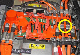
- Remove the bolt that secures the HV fuse ground strap to the body (torque 5.5 Nm).
- Release the edge clips (x2) that secure the HV harness to the body of the vehicle.
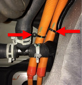
- Carefully release the grommet from the body.
- Remove the mid aero shield (refer to procedure).
- Remove and discard the screws (x4) that secure the B+ and B- HV
cables to the rear drive unit (torque 7 Nm).
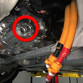
- Install protective caps over both HV cables to protect the terminals and seals.
- Release the cable ties (x2) that secure the HV cables to the
body of the vehicle.
- Lower the vehicle.
- Working from inside the vehicle, remove the HV harness.
Installation procedure is the reverse of removal, except for the following:
Caution: Replace all Patchbolt(s).
- Apply P-80 emulsion to the cable grommet and ensure that grommet is fully seated.
- Apply P-80 emulsion to the connector seals on the HV cables
before securing the HV cables to the drive unit.
Caution: Do not apply P-80 emulsion to the HV terminals.
.png)
READ NEXT:
 Handle and Cable Assembly - 40A Wall Connector (Remove and Replace)
Note: This procedure describes how to remove and replace
the 40A Wall Connector handle and cable assembly. For instructions
on how to remove and replace the 80A Wall Connector handle and cable
Handle and Cable Assembly - 80A Wall Connector (Remove and Replace)
Note: This procedure describes how to remove and replace
the 80A Wall Connector handle and cable assembly. For instructions
on how to remove and replace the 40A Wall Connector handle and cable
SEE MORE:
Replacing Cabin Air Filters
Model S has an air filter that prevents pollen, industrial
fallout, road dust, and other particles from entering the
cabin through the vents. Tesla recommends replacing
these filters every 2 years (every year in China). Cabin
filters can be purchased at the Tesla online store.
To replace the ca
Accelerator Assembly (Remove and Replace)
Removal
Remove the driver's footwell cover:
Left-hand drive (LHD) vehicles: Refer to
procedure.
Right-hand drive (RHD) vehicles: Refer to
procedure.
Disconnect the harness connector from the top of the accelerator
pedal assembly.
