Tesla Model S: HV Junction Box - Reed Switch - 1st Generation (Remove and Replace)
Tesla Model S (2012-2026) Service Manual / High Voltage System / HV Junction Box - Reed Switch - 1st Generation (Remove and Replace)
Note: This procedure only applies to vehicles with the 1st generation High Voltage Junction Box.
Special tools required for this procedure:
| Supplier | Part Number | Description |
| Bosch | 223-28550-TSL | Wiha (Torque Screwdriver .1 - .6Nm) |
- Perform the vehicle electrical isolation procedure (refer to procedure).
- Remove the HVJB cover (refer to procedure).
- Disconnect the reed switch from the master charger.
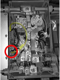
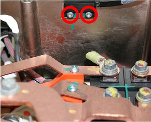
- Release the bolts (x2) that secure the reed switch to the HVJB
(torque 0.44 Nm / 3.89 in-lbs). Remove the reed switch from the
vehicle.
Installation procedure is the reverse of removal.
Caution: Use the Wiha torque screw driver or an equivalent tool to secure the reed switch to the HVJB.
READ NEXT:
 HV Rapid Mate Vehicle Side (Remove and Replace)
Removal
Remove the HV battery assembly(refer to procedure).
Lower the vehicle, but keep it in position to raise it in a
later step.
Remove the 2nd row seat cushion frame (refer to
HV Harness - HVJB to Charge Port - 2nd Generation
Warning: Only technicians who have been trained in High
Voltage Awareness are permitted to perform this procedure. Proper
personal protective equipment (PPE) and insulating HV gloves with a
HV Harness - Front Drive Unit to HVJB
Warning: Only technicians who have been trained in High
Voltage Awareness are permitted to perform this procedure. Proper
personal protective equipment (PPE) and insulating HV gloves with a
SEE MORE:
Bosch-Supplied Tools
223-34-36-08
Tesla part number:
n/a
Description:
Anti Static Mat/w Wrist Grounding Cord and Wrist Strap
Model:
n/a
Status:
Dis
Receiver Dryer and Desiccant (Remove and Replace)
Note: The desiccant bag in the receiver dryer is a
serviceable item and must be replaced every 2 years, whenever the
system is opened to ambient air for an extended time, or when an A/C
system leak has been fixed.
Note: The dessicant is located in the RH condenser.
Removal
© 2019-2026 Copyright www.tesms.org
