Tesla Model S: Master Cylinder (Remove and Replace)
Tesla Model S (2012-2026) Service Manual / Brakes / Master Cylinder (Remove and Replace)
Note: This procedure applies to vehicles with the vacuum brake booster only. If the vehicle has the electromechanical brake booster assembly, the master cylinder is part of the brake booster assembly. Refer to procedure 33031402 (refer to procedure).
Removal
- Remove master cylinder and reservoir assembly (refer to procedure)
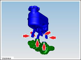
- Release reservoir to master cylinder fixing lugs (x4).
- Release reservoir from master cylinder connections (x2) and remove. Note: Place suitable absorbent material around the affected area to absorb any possible fluid spillage.
-
Remove and discard seals (x2) from master
cylinder.
Caution: Replace master cylinder seals.
- Installation procedure reverse of removal, except for the following: Warning: Only use cleaning agents and solvents in a well-ventilated area. Note: Clean the affected areas before installation.
- Bleed brakes (refer to procedure)
READ NEXT:
 Brake Hose - Flexible - Front - LH (Remove and Replace)
Warning: If the vehicle
has air suspension, activate "Jack" mode on the touchscreen before
raising and supporting the vehicle.
Removal
Remove the front LH wheel
(refer
Brake Hose - Flexible - Rear - LH (Remove and Replace)
Warning: If the vehicle
has air suspension, activate "Jack" mode on the touchscreen before
raising and supporting the vehicle.
Removal
Remove the rear wheel arch liner
Bleed Procedure - One Caliper (Remove and Replace)
Warning:
If the 12V power supply is disconnected, do not attempt to open
any doors with door glass in closed position. Failure to follow
this instruction could result in door glass shat
SEE MORE:
Assembly - Hood Latch Cover (Remove and Replace)
Removal
Open the hood for access.
Remove the lower carpet from the underhood storage area.
Gently lift up on the hood seal and remove the push pins (x2)
that secure the hood latch cover to crossmember.
HV Rapid Mate Vehicle Side (Remove and Replace)
Removal
Remove the HV battery assembly(refer to procedure).
Lower the vehicle, but keep it in position to raise it in a
later step.
Remove the 2nd row seat cushion frame (refer to procedure) .
Remove the high voltage junction box (HVJB) cover:
1st Gen
© 2019-2026 Copyright www.tesms.org
