Tesla Model S: Brake Hose - Flexible - Rear - LH (Remove and Replace)
Warning: If the vehicle has air suspension, activate "Jack" mode on the touchscreen before raising and supporting the vehicle.
Removal
- Remove the rear wheel arch liner (refer to procedure).
- Clean the areas that surround the connections at each end of the brake hose.
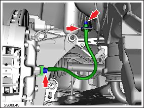
- Loosen the nut that secures the brake pipe to to the brake hose, then disconnect the brake pipe from the hose (torque 14 Nm). Caution: To prevent damage always use a suitable wrench to hold the backing nut when loosening pipes and unions. Caution: Plug pipe connections to prevent ingress of moisture or dirt. Note: Place suitable absorbent material around the affected area to absorb any possible fluid spillage.
- Note the orientation of the retaining clip that secures the brake hose to the fixed bracket. Remove the retaining clip and release the brake hose from the bracket.
-
Remove and discard the bolt and sealing washers
(x2) that secure the brake hose to the caliper (torque 34 Nm).
Caution: If brake fluid is spilled on a painted surface, wash off immediately with clean water.
- Note the orientation of the brake hose. Remove the brake hose from the vehicle.
Caution: Plug pipe connections to prevent ingress of moisture or dirt.
InstallationInstallation procedure is the reverse of removal, except for the following:
Note: Clean the affected areas before installation.
Warning: Replace both sealing washers.
Caution: Ensure that the brake hose is oriented correctly with no excessive twist or bends.
Caution: Ensure that the retaining clip that secures the brake hose to the fixed bracket is oriented correctly. Bleed the brake caliper (refer to procedure).
READ NEXT:
 Bleed Procedure - One Caliper (Remove and Replace)
Warning:
If the 12V power supply is disconnected, do not attempt to open
any doors with door glass in closed position. Failure to follow
this instruction could result in door glass shat
Bleed Procedure - System (Remove and Replace)
Warning: If the 12V
power supply is disconnected, do not attempt to open any doors
with door glass in closed position. Failure to follow this
instruction could result in door glass shat
Vacuum Brake Booster Assembly (Remove and Replace)
Caution: This procedure
describes how to remove and replace the vacuum brake booster
only. If the vehicle is equipped with an electromechanical brake
booster assembly, refer to procedur
SEE MORE:
Charging equipment communication lost
Check power source and charging equipment
Charging stopped because communication between the vehicle and the external
charging equipment was
interrupted.
Confirm whether the external charging equipment is powered by looking for any
status lights, displays, or other
indicators on the equipment.
Hub - Rear - LH (Remove and Replace)
Special tool(s) required for this procedure:
Supplier
Part Number
Description
Tesla
1062500-00-A
Magnetic Field Viewing Card
Tesla
1082171-00-A
S-hook
Warning: If
