Tesla Model S: Mount - Front Drive Unit - LH (Adjust)
Note: This procedure assumes that the RH mount has been replaced, but that the shim tools cannot be repositioned to verify proper clearance. If this happens, follow this procedure to adjust the LH side motor mount.
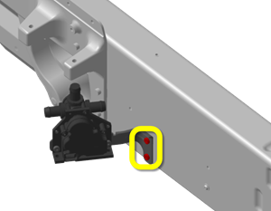
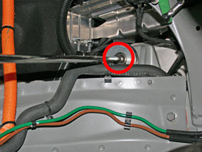
- Release the 2 bolts that secure the 4-way valve bracket to the body.
- Raise the vehicle and remove the front LH wheel.
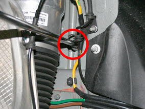
- Release the plastic rivets that secure the rear of the upper front arch liner, then pull the arch liner forward.
- Looking upward through the wheewell, inspect the rear of the LH motor
mount. Note whether it has a backing plate that secures the nuts; this
information will be used later in the procedure.
- Lower the vehicle.
- Lower the support jack approximately halfway.
- Position the LH strap:
Note: Work from the underhood area while an assistant works from the LH wheelwell.
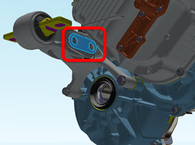
- Slide the strap between the LH motor mount and the front drive unit.
.png)
- Have the assistant slide the strap inward, as close to the differential housing as possible. Caution: Ensure that there are no coolant hoses between the strap and the front drive unit.
- Reach behind the front cross car beam and pull the strap up and over the top of the support jack.
- Secure the two ends of the strap with the carabiner.
- Slide the strap so that the carabiner is approximately 6 inches (150 mm) above the front cross car beam.
- Slide the strap between the LH motor mount and the front drive unit.
- Raise the support jack until the LH strap is completely taut.
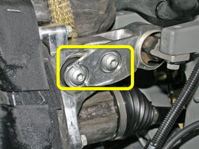
- Loosen the 2 adjustment bolts on the LH mount until the weight of the
motor shifts onto the strap.
Note: If the LH motor mount does not have a backing plate, have an assistant use a 15 mm wrench to restrain the nuts on the rear of the motor mount while loosening the bolts.
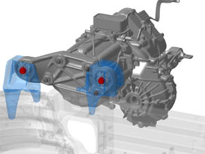
- Loosen the 4 bolts that secure the RH motor to the mount.
.png)
- Working from the underhood area, loosen the forward upper bolt.
- Working from the underhood area, loosen the forward lower bolt.
- Working from the RH wheelwell, loosen the rear upper bolt.
- Working from the RH wheelwell, loosen the rear lower bolt.
- Working from the RH wheelwell, use socket wrench with an extension to
loosen the 2 bolts that secure the mount to the body.
- Loosen the rear bolt and washer.
- Loosen the front bolt.
- Loosen the rear bolt and washer.
- Position the 3 shim tools in between the RH motor mount and body.
Note: These tools ensure proper clearance. Leave them in place until prompted to remove, after all 6 bolts for the mount are fully torqued.
.png)
- Working from the underhood area, position the 2-pronged shim around
the RH motor mount front bushing.
.png)
- Reach beneath the motor and position the hook shim tool between the mount and outer bushing.
- Reach downward between the V-brace and cross brace and position the straight shim tool between the mount and inner bushing.
- Working from the underhood area, position the 2-pronged shim around
the RH motor mount front bushing.
- Working from the wheelwell, fully torque the bolts that secure the mount to the body (torque 120 Nm).
- Attach the 15 mm ratchet tool to a torque wrench.
Caution: Ensure that the attachment is 90 degrees perpendicular to the torque wrench when using the tool.
.png)
- Working from the underhood area, fully torque the 4 bolts that secure
the motor to the mount (torque 75 Nm).
.png)
- Working from the underhood area, use the ratchet and torque wrench to secure the upper front bolt.
- Working from the wheewell, secure the lower rear bolt.
- Working from the wheewell, secure the upper rear bolt.
- Working from the underhood area, use the ratchet and torque wrench to secure the lower front bolt.
- On the LH side motor mount, fully torque the 2 adjustment bolts to 50 Nm.
- Remove the shim tools, then attempt to reinstall them:
- If all 3 shim tools can be easily installed and removed, the motor is properly adjusted.
- If the shim tools can not be easily installed and removed, repeat this procedure.
READ NEXT:
 Gearbox Fluid - Front (Remove and Replace)
Special tool required for this procedure:
Supplier
Part Number
Description
Tesla
1054946-0
Driveshaft Assembly - Front - LH (Remove and Replace)
Special tools required for this procedure:
Supplier
Part Number
Description
Tesla
1057312-
Driveshaft Assembly - Front - RH (Remove and Replace)
Warning: If the vehicle has air suspension, activate "Jack"
mode on the touchscreen before raising and supporting the vehicle.
Removal
Remove the RH front wheel (refer to procedu
SEE MORE:
Harness - Instrument Panel (Remove and Replace)
Removal
Remove the driver's and front passenger's seats (refer to
procedure).
Remove the center console assembly (refer to procedure).
Remove the IP carrier (refer to procedure).
Note: These graphics show a LHD vehicle produced in
mid-2014. Earli
HV Rapid Mate Vehicle Side (Remove and Replace)
Removal
Remove the HV battery assembly(refer to procedure).
Lower the vehicle, but keep it in position to raise it in a
later step.
Remove the 2nd row seat cushion frame (refer to procedure) .
Remove the high voltage junction box (HVJB) cover:
1st Gen
