Tesla Model S: Wiper Motor Assembly (Remove and Replace)
Tesla Model S (2012-2026) Service Manual / Electrical / Wiper Motor Assembly (Remove and Replace)
Removal
- Ensure that the wipers are in the off position by rotating the end of the left-hand steering column lever toward you.
- Open the hood to the service position.
- Remove the cowl screen panel (refer to procedure).
- Remove the LH strut (RH strut for RHD) (refer to procedure).
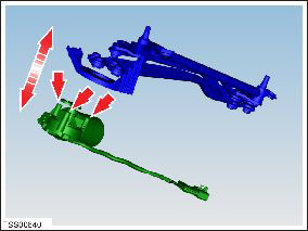
- Remove the bolts (x3) that secure the wiper motor assembly to
the bulkhead (torque 6 Nm).
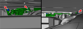
- Carefully release the wiper motor assembly and turn it to access the harness connector.
- Disconnect the harness connector from the wiper motor assembly.
- Remove the wiper motor assembly. Caution: Do not damage the harness that is connected to the wiper motor assembly.
- If needed, remove the screws (x3) that secure the wiper motor to the mounting bracket (torque 10 Nm).
- Remove the wiper motor.
Installation procedure is the reverse of removal, except for the following:
- Clean the affected areas before installation.
- Ensure that the wipers are set back to the Auto position by rotating the end of the left-hand steering column lever away from you.
READ NEXT:
 Pump - Windshield Washer Reservoir (Remove and Replace)
Removal
Remove the front LH upper wheel arch liner (refer to procedure).
Position a container to collect any spillage.
Disconnect the washer pump connector.
Release the washer
Reservoir - Windshield Washer (Remove and Replace)
Removal
Remove the rear center underhood apron (refer to procedure).
Remove the plastic rivet that secures the reservoir neck to the
suspension shock tower.
Nozzle - Windshield Washer Jet (Remove and Replace)
Removal
Remove the hood acoustic panel (refer to procedure).
Disconnect the washer jet pipe from the T-piece.
Release t
SEE MORE:
Camera Location
Model S is equipped with a rear view camera located
above the rear license plate.
Whenever you shift into Reverse, the touchscreen
displays the view from the camera. Lines show your
driving path based on the position of the steering yoke.
These lines adjust as you move the steering yoke.
Model
To Use the Mobile App
To set up the Tesla mobile app to communicate with
your Model S:
1. Download the Tesla mobile app to your phone.
2. Log in to the Tesla mobile app by entering your Tesla
account credentials.
3. Enable mobile access to your Model S by touching
Controls > Safety > Mobile Access (see Control
© 2019-2026 Copyright www.tesms.org
