Tesla Model S: 200A Fuses - Wall Connector (Remove and Replace) - Installation
Tesla Model S (2012-2026) Service Manual / External Charging Connectors / 200A Fuses - Wall Connector (Remove and Replace) / 200A Fuses - Wall Connector (Remove and Replace) - Installation
Installation
- Clean the contact surfaces of the new upper and lower bus bars with alcohol wipes.
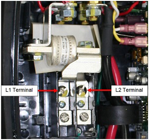
- Position the new inner fuse. Install the screw at the L2 terminal (torque 3 Nm).
- Install the inner wire's ring lug on the inner contactor stud.
Caution: Position both ring lugs so that the wires point toward the front of the unit at a 45-degree angle, allowing a gap between the inner wire and the outer bus bar. The wires must not touch the bus bars directly. Caution: Always install the bus bar first and the ring lug second. Installing the ring lug first can result in excessive resistance and overheating.
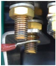
- Hold the inner wire in position while tightening the nut (torque 5 Nm).
- Use a paint or ink pen to mark the torque position after reassembly, using a different color than manufacturing (manufacturing usually uses yellow). Use one continuous motion to mark the bolt, washer, nut, and bus bar.
- Reinstall the insulator sheet at its original location.
- Repeat steps 2-5 using the L1 terminal for the outer fuse.
- Ensure that the ring lugs are correctly reinstalled to the same location they were before beginning this procedure.
- Use a multimeter to check the resistance between terminals L1
and L2. The resistance should be at least 100 KOhm. If the
resistance is less than 100 KOhm, check for an electrical short due
to improper installation or defective insulation.
- Reinstall the Wall Connector's cover and security screws.
- Turn on the electricity at the circuit breaker.
- Check the front diagnostic lights on the Wall Connector cover. When it is not plugged into the vehicle, the topmost green LED should be steady (not flashing).
- Charge the vehicle with the Wall Connector for 2-3 minutes to verify proper operation of the Wall Connector.
READ NEXT:
 Firmware Update - CHAdeMO Charging Adapter
Tools required:
12V power supply
Laptop with Toolbox 2.0 or higher
USB-CAN dongle
CHAdeMO CAN programming connector
CAN Setup
Connect the USB-CAN dongle to a laptop that i
SEE MORE:
General Fitting Instructions
Component removal
Whenever possible, clean components and surrounding area before removal.
Cap off openings exposed by component removal.
Immediately seal fuel, oil or hydraulic lines when apertures are
exposed; use plastic caps or plugs to prevent loss of fluid and
ingress of dirt.
Interior Emergency Release
An illuminated interior release button inside the front
trunk allows a person locked inside to get out.
Press the interior release button to open the front trunk,
then push up on the hood.
NOTE: The interior release button glows following a brief
exposure to ambient light.
WARNING: People shou
© 2019-2026 Copyright www.tesms.org
