Tesla Model S: Vacuum Brake Booster Assembly (Remove and Replace)
Tesla Model S (2012-2026) Service Manual / Brakes / Vacuum Brake Booster Assembly (Remove and Replace)
Caution: This procedure describes how to remove and replace the vacuum brake booster only. If the vehicle is equipped with an electromechanical brake booster assembly, refer to procedure 33031402 (refer to procedure).
Removal
- Remove the master cylinder and reservoir assembly (refer to procedure).
-
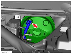
Release the clip that secures the brake booster
hose.
Caution: Plug pipe connections to prevent ingress of moisture or dirt.
- Remove the brake light switch (refer to procedure). Caution: The brake light switch is a one time use component. Ensure that a new switch is used during reinstallation.
-
Remove the spring clip from the clevis pin.
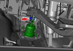
- Depress the brake pedal for clearance and remove the clevis pin.
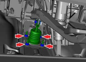
-
Remove and discard the nuts (x4) that secure
the pedal to the brake booster assembly (torque 23 Nm).
- Remove the brake booster assembly from the vehicle by maneuvering it through the top of the frunk.
Installation procedure is the reverse of removal, except for the following:
Note: Clean the affected areas before installation.
Caution: Replace all nylon-insert locknuts.
- Replace the brake light switch.
- Check brake operation before driving vehicle.
READ NEXT:
 Vacuum Pump (Remove and Replace)
Warning: If the vehicle
has air suspension, activate "Jack" mode on the touchscreen before
raising and supporting the vehicle.
Removal
Remove the underhood storage unit
Bracket - Vacuum Pump (Remove and Replace)
Warning: If the vehicle
has air suspension, activate "Jack" mode on the touchscreen before
raising and supporting the vehicle.
Removal
Remove the front skid plate
(ref
Reservoir - Master Cylinder (Remove and Replace)
Removal
Remove the master cylinder and reservoir
assembly
(refer to procedure).
Release the reservoir to master cylinder fixing
lugs (x4).
Release the reservoir
SEE MORE:
Special Tools - HV Battery Alignment Rods
The HV battery alignment rods assist in aligning the HV battery during
installation.
Note: This tool is intended to be used by 2 technicians.
To use the alignment rods:
Position the table under the vehicle until the bolt holes in the battery
and vehicle are roughly aligned. Do not lo
Location of Airbags
Airbags are located in the approximate areas shown below. Airbag warning
information is printed on the sun visors.
Model S is equipped with an airbag and lap/shoulder belt at both front seating
positions. The airbag is a
supplemental restraint at those seating positions. All occupants, including
© 2019-2026 Copyright www.tesms.org
