Tesla Model S: Light - Fog/Reverse - Rear - LH (Remove and Replace)
Tesla Model S (2012-2026) Service Manual / Electrical / Light - Fog/Reverse - Rear - LH (Remove and Replace)
Removal
- Remove the liftgate applique (refer to procedure).
- Remove the tailgate lower finisher (refer to procedure).
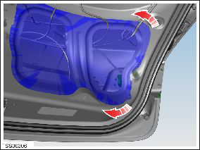
- Release the watershield for access to the fog/reverse lamp.
Note: A new watershield might be required if the adhesive is unable to secure it in position during reinstallation.
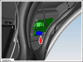
- Disconnect the fog/reverse light connector.
- Remove the nuts (x4) that secure the lamp assembly to the
tailgate panel (torque 4 Nm).
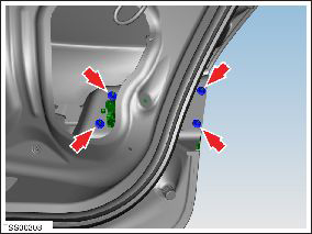
- Remove the fog/reverse lamp assembly.
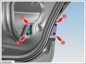
Installation procedure is the reverse of removal, except for the following: Caution: Ensure that the foam gasket is completely flush with the fog/reverse light before installing.
- When securing the lamp to the tailgate panel, secure the
nuts in the order shown (torque 4 Nm).
READ NEXT:
 Lamp - Side Repeater - Front - LH (Remove and Replace)
Removal
Using a suitable tool carefully release fixing lugs (x2)
securing side repeater to front fender. NOTE: Wheel arch liner
removed for clarity.
Caution:
Lamp - Reflex - Rear - LH (Remove and Replace)
Removal
Remove rear fascia assembly for access (refer to procedure)
Release clips (x2) securing reflex lamp to rear fascia.
Remove reflex lamp.
Lamps - Fog - Front - Adjust
Position the vehicle for adjusting the fog lamps:
In a darkened area.
On a level surface.
Perpendicular to a wall that has a matte white
surface. The
SEE MORE:
Assembly - Frame - Instrument Cluster (Remove and Replace)
Removal
Remove driver side lower dash trim (refer to procedure)
Remove the instrument panel side covers (refer to procedure)
Remove the A-pillar middle trim panels (refer to procedure)
Remove the A-pillar upper trim panels (refer to procedure)
Remove the lower binnac
Hose - Front HVAC - Drain (Dual Motor) (Remove and Replace)
Remove
Perform the electrical isolation procedure (refer to procedure).
Remove the RH steering brace:
Remove the bolt that secures the steering brace to
the subframe (torque 26 Nm).
© 2019-2026 Copyright www.tesms.org
