Tesla Model S: Module - Sunroof Controller (Remove and Replace)
Tesla Model S (2012-2026) Service Manual / Electrical / Module - Sunroof Controller (Remove and Replace)
Removal
- Remove the body control module (BCM) (refer to procedure)
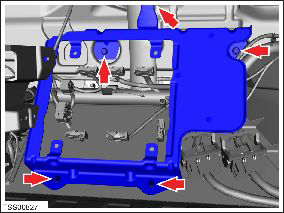
- Remove the 4 bolts and 1 nut that secure the sunroof controller
mounting bracket to the body (torque 8 Nm).
- Carefully turn the mounting bracket over.
- Remove the 3 nuts that secure the controller to the bracket
(torque 5 Nm).
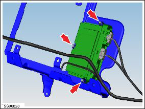
- Disconnect the 2 controller harness connectors.
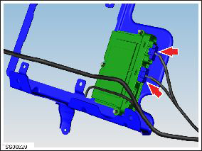
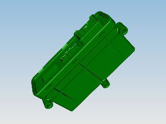
- Remove the controller from the mounting bracket.
Installation procedure is the reverse of removal, except for the following: Use Toolbox to update or redeploy the firmware:
- If the vehicle is not running the latest firmware, run the "Vehicle Firmware Update" procedure.
- If the vehicle is running the latest firmware, run the "Firmware Redeploy" procedure.
READ NEXT:
 Module - Sunroof Controller (RHD) (Remove and Replace)
Warning: If the 12V power supply is disconnected, do
not attempt to open any doors with door glass in closed position.
Failure to follow this instruction could result in door glass
shat
Module - Air Suspension - ECU (Remove and Replace)
Warning: If the 12V power supply is disconnected, do
not attempt to open any doors with door glass in closed position.
Failure to follow this instruction could result in door glass
shat
Module - Air Suspension - ECU (Remove and Install)
Warning: If the 12V power supply is disconnected, do
not attempt to open any doors with door glass in closed position.
Failure to follow this instruction could result in door glass
shat
SEE MORE:
Master Charger - RH - 2nd Generation (Remove and Replace) - Removal
Note: This procedure describes how to remove and install
the 2nd generation master charger. If the vehicle is equipped with a
1st generation master charger, refer to procedure 44100202 (refer to
procedure).Warning: Only technicians who have been trained in High
Voltage Awareness are
Compressor - Air Suspension (Remove and Replace)
Warning: If the vehicle has air suspension, activate "Jack"
mode on the touchscreen before raising and supporting the vehicle.
Removal
Raise and support the vehicle (refer to procedure)
Depressurize air suspension (refer to procedure)
Remove underhood storage unit for acces
© 2019-2026 Copyright www.tesms.org
