Tesla Model S: PCB - Door - Exterior Handle - Front - LH (Remove and Replace)
Tesla Model S (2012-2026) Service Manual / Closures / PCB - Door - Exterior Handle - Front - LH (Remove and Replace)
Removal
- Remove fork and control link for acces (refer to procedure)
- Remove screws (x3) securing PCB to housing (torque 1.5 Nm).
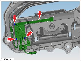
- Release PCB pressure sensor from housing and disconnect wiring.
- Remove assembly.
- Installation procedure is the reverse of removal, except for the following.
- Clean mating face of PCB touch sensor and housing.
- Remove adhesive backing strip from sensor and secure to housing.
PCB - Door - Exterior Handle - Rear - LH (Remove and Replace)
Removal- Remove fork and control link for acces (refer to procedure)
- Remove screws (x3) securing PCB to housing (torque 1.5 Nm).
- Release PCB pressure sensor from housing and disconnect wiring.
- Remove assembly.
- Installation procedure is the reverse of removal, except for the following.
- Clean mating fact of PCB touch sensor and housing.
- Position PCB to housing and secure with two screws. Connect the PCB wiring connector.
- Remove adhesive backing strip from sensor and secure to housing.
READ NEXT:
 Press Sensor - Door - Exterior Handle - Front - LH (Remove and Replace)
Removal
Remove door handle for access (refer to procedure)
Position handle assembly on a soft working surface.
Remove door handle rear seal.
Remove cable ties securing door pressu
Press Sensor - Door - Exterior Handle - Rear - LH (Remove and Replace)
Removal
Remove door handle for access (refer to procedure)
Position handle assembly on a soft working surface.
Remove door handle rear seal.
Remove cable ties securing door pressu
Position Sensor - Door - Exterior Handle - Front - LH (Remove and Replace)
Removal
Remove door handle for access (refer to procedure)
Remove door handle rear seal.
Remove control link pivot pin to allow control link to be
released from housing.
Posit
SEE MORE:
Rear View Mirror - 2nd Generation (Remove and Replace)
Note: This procedure describes how to remove and replace
the 2nd generation rear view mirror. If the vehicle is equipped with
a 1st generation rear view mirror, refer to procedure 15050202 (refer
to procedure).Removal
Remove the front cover by pulling straight down to relea
Speaker - Front Door Premium Audio - LH/RH (Remove and Replace)
Removal
Remove door trim panel (refer to procedure)
Remove 4 screws securing speaker to spacer ring (torque 1.8 Nm).
Remove connector from door speaker.
Remove front door speaker.
Remove 4 screws securing trim ring to door shell (torque 1.8
Nm).
© 2019-2026 Copyright www.tesms.org
