Tesla Model S: Active Louver - Center (Remove and Replace)
Tesla Model S (2012-2026) Service Manual / Thermal Management / Active Louver - Center (Remove and Replace)
Removal
- Remove the front bumper (refer to procedure).
- Remove the radiator (refer to procedure).
- Remove the ankle catcher (refer to procedure).
- Remove the plastic rivets (x3) that secure the active center louver to the carrier.
- Remove the bolts (x8) that secure the active center louver to
the carrier (torque 11 Nm).
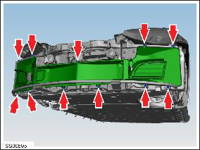
- Remove the active center louver assembly.
- Place the active center louver assembly assembly on a soft, clean surface with the front of the duct assembly facing down.
- Remove the screws (x2) that secure the LH louver vent motor to
the active center louver assembly (torque 1 Nm).
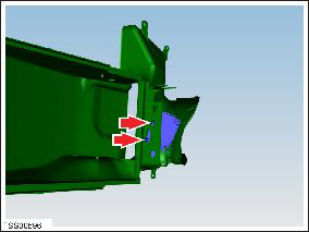
- Remove the louver vent motor.
- Release the bolt that secures the horn bracket to the active
center louver assembly assembly (torque 5 Nm).
Note: Do not release the nut that secure the horn to the bracket.
.png)
- Remove the horn and bracket by maneuvering them out through the circular hole in the radiator duct assembly.
Installation procedure is the reverse of removal, except for the following:
Caution: If installing an active center louver assembly with circular cutouts for 2nd generation horns, install the 2nd generation horns. Do not leave the cutouts unplugged.
- Power cycle the thermal controller:
- Remove the Thermal System Controls fuse (F22).
- Wait approximately 30 seconds.
- Reinstall fuse F22.
- In the Toolbox "Louver Shutter Operation" panel, run the "Recalibrate Louver Shutters" procedure in Toolbox.
READ NEXT:
 Duct - Condenser LH (Remove and Replace)
Removal
Remove the front fascia assembly (refer to procedure).
Remove the bolts (x4) that secure the duct to the condenser
housing (torque 16 Nm on vehicles equipped with a magnesium
Motor - Active Louver - Front Fascia (Remove and Replace)
Removal
Remove front fascia active louver vent (refer to procedure)
Remove screws (x3) securing louver drive motor to vent assembly
(torque 1 Nm).
Vent - Motorized - Front Fascia - LH (Remove and Replace)
Removal
If the vehicle is equipped with 1st generation front fascia
applique, remove front fascia applique (refer to procedure) .
Remove ankle catcher foam, if equipped.
SEE MORE:
Reservoir - Windshield Washer (Remove and Replace)
Removal
Remove the rear center underhood apron (refer to procedure).
Remove the plastic rivet that secures the reservoir neck to the
suspension shock tower.
Remove the washer pump from the reservoir (refer to pr
Door Mirror Assembly - LH (Replace)
Installation
Installation procedure is the reverse of removal, except for the
following:
Inspect the mirror area of the door panel. Install 2 nylon shims
(1026519-00-A) and a strip of black felt tape if they are not
present in the area.
© 2019-2026 Copyright www.tesms.org
