Tesla Model S: Cross Car Beam (Remove and Replace)
Tesla Model S (2012-2026) Service Manual / Instrument Panels and Pedals / Cross Car Beam (Remove and Replace)
Removal
- Remove the IP carrier (refer to procedure).
- Remove the center console (refer to procedure).
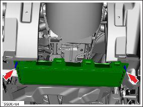
- Remove the nuts (x2) that secure the driver knee airbag. Retain
the washers (x2). Disconnect the harness connector and remove the
airbag from the vehicle (torque 10.5 Nm).
- Remove the nuts (x2) that secure the passenger knee airbag. Disconnect the harness connector and remove the airbag from the vehicle (torque 10.5 Nm).
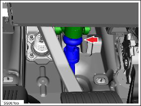
- Remove the bolt that secures the steering column to the
intermediate shaft joint (torque 33 Nm).
- Carefully remove the steering wheel and column assembly. Caution: To prevent damage, do not allow the steering wheel and column assembly to rotate while it is removed.
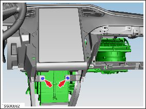
- Remove the bolts (x2) that secure the HVAC assembly to the cross
car beam (torque 10 Nm).
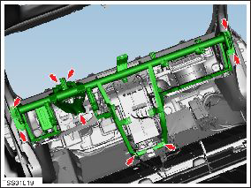
- Remove the bolts (x9) that secure the cross car beam to the body (torque 27 Nm).
- Release the cross car beam from the body and retain the spacer from between the LH 'A' post and the cross car beam.
- Remove the cross car beam.
Installation procedure is the reverse of removal.
READ NEXT:
 Assembly - Frame - Instrument Cluster (Remove and Replace)
Removal
Remove driver side lower dash trim (refer to procedure)
Remove the instrument panel side covers (refer to procedure)
Remove the A-pillar middle trim panels (refer to proce
Trim - Touch Screen Surround (Remove and Replace)
Removal
Remove the MCU/touch screen (refer to procedure).
Remove the screws (x6) that secure the touch screen surround
(torque 4 Nm).
Cut the cable tie that secures the Bluetooth
Face Level Vent - Driver's - Outer (Remove and Replace)
Removal
Remove the driver side lower dash trim (refer to procedure).
Remove the lower binnacle cover.
Remove the 2
SEE MORE:
Assembly - Bin - Storage Center Compartment (Remove and Replace)
Removal
Remove center console carpet.
Caution: Apply contact adhesive to mating faces if
bond has been broken.
Release clips (x4) securing closing panel to dash.
Caution: Take care not to damage component(s).
Caution: Repl
Badge - Ludicrous Speed (Retrofit)
Special tool required for this procedure:
Supplier
Part Number
Description
Tesla
1054190-00-A
FEELER GAUGES
Procedure
Note: This procedure onl
© 2019-2026 Copyright www.tesms.org
