Tesla Model S: Front Drive Unit (From Below) (Remove and Install) - Removal
Special tools required for this procedure:
| Supplier | Part Number | Description |
| Bosch | FMG-750 | Transmission Jack 750 Kg Europe only |
| Tesla | 1053350-00-A | Transmission Jack Cradle Adapter Plate Europe only |
| Tesla | 1063141-00-A | 1/2 Ton Economy Transmission Jack North America, APAC only |
| Tesla | 1048391-00-A | Drive Unit Dual Motor Cradle - Delrin white |
| Tesla | 1056566-00-A | Locating Shim Set, Front Motor |
| Tesla | 1056542-01-A | Special 15mm Ratchet Wrench |
-
Remove the center cap from the front LH wheel
and loosen the axle nut.
.png)
- Recover refrigerant from the vehicle (refer to procedure).
- Remove the front subframe (refer to procedure).
- Remove the 12V battery bracket beam (refer to procedure).
-
Release the 2 fir tree clips that secure the
12V positive harness to the front crossmember.
-
Move the 12V positive harness to the RH side of
the vehicle to keep it out of the working area.
-
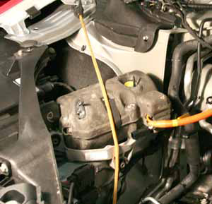
Release the 4 bolts that secure the coolant
reservoir to the front crossmember (torque 6 Nm). Do not remove the
reservoir at this time.
.png)
-
Carefully lift up the coolant reservoir and
disconnect the coolant level sensor harness.
.png)
-
Ensure that the cap on the reservoir is
properly secured, then pull the reservoir forward into the underhood
area.
Note: The reservoir
hose is routed behind the drive unit hose. Note the routing
of the hoses and ensure that they are routed correctly
during reinstallation.
.png)
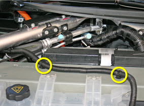
-
Gently pull down on the 2 coolant hoses to
release the clips (x4) that secure them to the front crossmember.
.png)
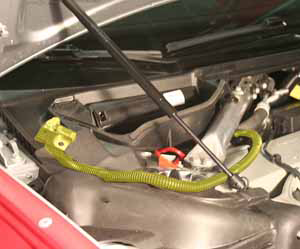
-
Release the clip that secures the coolant
reservoir hose to the A/C line.
.png)
-
On the LH side of the 3-way fitting, clamp the
coolant hose that leads to the differential housing. Remove the hose
from the front drive unit and and plug the nipple.
.png)
.png)
-
Move the coolant reservoir to the LH side of
the vehicle and secure it out of the working area.
Caution: The reservoir is still secured to 2 coolant hoses.
.png)
- On the LH side of the drive unit, clamp the coolant hose. Remove the hose and plug the nipple. Tip: Use flexible hose clamp pliers to release the locking ring.
-
Move the clamped drive unit coolant hose to the
RH side of the vehicle so that it is out of the working area.
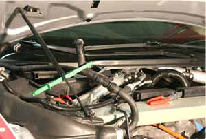
-
Release the clip that secures the LH A/C line
to the compressor HV harness.
.png)
- Release the 2 nuts that secure the A/C lines to the compressor (torque 10 Nm). Plug both holes and cap both lines.
-
Disconnect the compressor LV harness.
.png)
-
Release the ground strap from the A/C
compressor bracket (torque 7 Nm).
.png)
-
Release the edge clip that secures the LV
harnesses to the compressor bracket.
.png)
-
Release the fir tree clip that secures the LV
harnesses to the top of the front drive unit.
.png)
- Wrap the LV harnesses around the RH hood strut so that they are out of the working area.
-
Have an assistant support the compressor.
Release the 3 bolts that secure the A/C compressor bracket to the
front drive unit (torque 10 Nm).
-
Move the compressor and bracket to the RH side
of the vehicle and secure them outside of the working area.
- Raise the vehicle to access the wheelwells.
- Remove the front axle nuts and washers (torque 205 Nm).
-
Release the 4 screws that secure the HV cables
to the front drive unit (torque 7 Nm).
Caution: During reinstallation, carefully inspect the connector seals. If any are damaged, replace them.
Caution: Apply P-80 emulsion to the connector seals on the HV cables before securing the HV cables during reinstallation.
Caution: Do not apply P-80 emulsion to the HV terminals.
.png)
- Fully raise the vehicle.
- Remove the lower RH section of the acoustic cover from the drive unit.
- Drain the gearbox fluid.
-
Clamp the 2 coolant hoses that lead to coolant
pump 4.
.png)
- Release the locking rings that secure the coolant hoses to coolant pump 4.
- Remove the LH axle shaft (refer to procedure).
- Remove the jackshaft (refer to procedure).
- Europe only: Install the adapter plate onto the transmission jack.
-
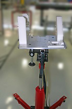
Install the drive unit cradle onto the
transmission jack.
Non-European jack shown
- Position the transmission jack fixture underneath the drive unit.
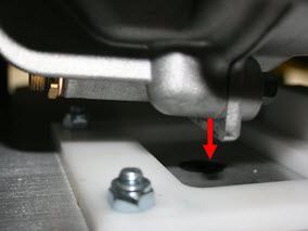
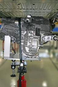
-
Raise the transmission jack to support the
weight of the drive unit. Ensure that the ridge on the base of the
drive unit fits into the channel on the transmission jack.
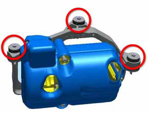
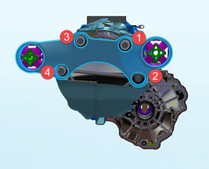
-
Release the bolts (x4) that secure the motor to
the RH mount.
Note: Do not fully remove the bolts from the mount; loosen the bolts in the order shown so that the motor is no longer supported by the mount. The RH motor mount is not removed in this procedure.
- Release the bolts (x2) that secure the LH motor mount to the body (torque 50 Nm).
-
Lower the transmission jack and secure the
drive unit with the strap.
READ NEXT:
 Front Drive Unit (From Below) (Remove and Install) -
Installation
Front Drive Unit (From Below) (Remove and Install) -
Installation
Installation
Installation procedure is the reverse of removal,
except for the following:
Use alcohol wipes to clean the mating surfaces between the RH
motor moun
Front Drive Unit (From Below) (Remove and Replace)
Special tool required for this procedure:
Supplier
Part Number
Description
SEE MORE:
Brightwork - Body side - LH (Remove and Replace)
Removal
Release the top of the front and rear door seals.
Note: Components have been removed in this graphic
to aid clarity.
Note: The following image shows the rear door
seal.
Rem
Bash Plate - Front - Extrusion (Remove and Replace)
Removal
Raise and support the vehicle
(refer to procedure).
Remove and discard the bolts (x2) that secure
the bash plate extrusion to the front subframe (10 Nm).
Remove the bash plate extrusion.
Installation
