Tesla Model S: Fusebox - Battery (RHD) (Remove and Replace)
Warning: If the 12V power supply is disconnected, do not attempt to open any doors with door glass in closed position. Failure to follow this instruction could result in door glass shatter.
Note: Before disconnecting the 12V power supply, ensure that the driver's door window is fully open. Failure to follow this instruction could result in vehicle lockout.
Removal
- Remove the 12V battery (refer to procedure).
- Pull back the LH front upper wheel arch liner for access (refer to procedure). Note: The wheel arch liner does not need to be completely removed.
- Remove the nut that retains the battery fusebox cover.
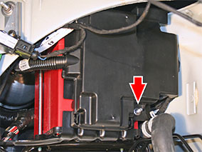
- Remove the battery fusebox cover.
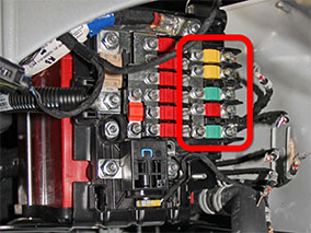
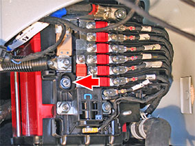
- Record the positions of the small-gauge cables at the RH side of
the fusebox.
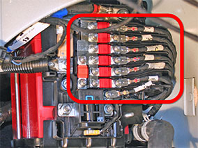
- Remove the nuts that retain the small-gauge cables and fuses at
the RH side of the fusebox (torque 5 Nm).
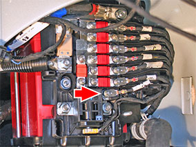
Note: After removing the lowest cable, temporarily reinstall the nut loosely. This prevents the bolt from falling out of the back of the fusebox when it is removed.
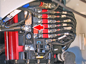
- Remove the wire separator for access to the inboard cables and
fuses.
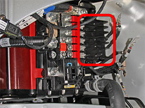
- Remove the nuts that retain the inboard wires and fuses at the
RH side of the fusebox (torque 5 Nm).
Note: The middle green fuse, fuse F82, is for the air suspension compressor. Vehicles with coil suspension do not have a wire connected to fuse F82.
- Remove the nuts (x2) that secure the pyrotechnic fuse (torque 12
Nm). Disconnect the pyrotechnic fuse connector.
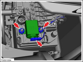
- Remove the pyrotechnic fuse.
- Remove the nut that secures the DCDC harness to the fusebox
(torque 12 Nm).
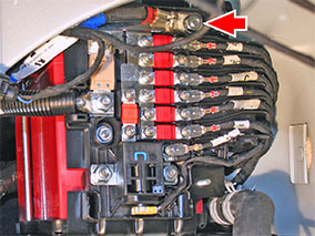
- Remove the nut that secures the battery positive cable to the
fusebox (torque 10 Nm).
Note: After removing the battery positive cable, temporarily reinstall the nut loosely. This prevents the positive terminal adaptor and square head bolt from falling out of the back of the fusebox when it is removed.
- Remove the nut that secures the fusebox to the fusebox bracket
(torque 5 Nm).
- Remove the fusebox.
Installation procedure is the reverse of removal, except for the following:
- Before installing the fusebox, temporarily install the nut on the battery positive terminal loosely. This prevents the positive terminal adaptor and square head bolt from falling out of the back of the fusebox before it is installed.
- Before installing the fusebox, temporarily install the nut on lowest small-gauge cable loosely. This prevents the bolt from falling out of the back of the fusebox before it is installed.
READ NEXT:
 12V Battery Bracket Beam (Remove and Replace)
Removal
Remove the 12V battery (refer to procedure).
Release the 2 bolts that secure the 12V battery bracket to the
front crossmember (torque 15 Nm).
Harness - Instrument Panel (Remove and Replace)
Removal
Remove the driver's and front passenger's seats (refer to
procedure).
Remove the center console assembly (refer to procedure).
Remove the IP carrier (refer to procedure).
Harness - Body Front Left (Remove and Replace)
Note: This procedure explains how to remove the front
left body harness from a vehicle with the 2nd Generation High
Voltage configuration. Vehicles with the 1st Generation High
Voltage
SEE MORE:
Charging Locations
To display charging locations on the map, touch the
map's search bar, then touch Charging. Charging
locations are shown in a list (with the closest charging
location at the top of the list) and represented by
corresponding pins on the map. Touch a pin to display
more information, navigate to it
Driveshaft Assembly - Front - RH (Remove and Replace)
Warning: If the vehicle has air suspension, activate "Jack"
mode on the touchscreen before raising and supporting the vehicle.
Removal
Remove the RH front wheel (refer to procedure).
While having an assistant press the brake pedal, loosen the RH
front axle nut, but do n
