Tesla Model S: HV Junction Box - 1st Generation (Remove and Replace)
Warning: Only technicians who have been trained in High Voltage Awareness are permitted to perform this procedure. Proper personal protective equipment (PPE) and insulating HV gloves with a minimum rating of class 00 (500V) must be worn any time a high voltage cable is handled. Refer to Tech Note TN-15-92-003, "High Voltage Awareness Care Points" for additional safety information.
Removal
Note: The Slave charger is not installed on all vehicles, but it may appear in the graphics for this procedure.
- Perform the vehicle electrical isolation procedure (refer to procedure).
- Remove the HVJB cover (refer to procedure).
- Position the coolant hose aside to access to the HV junction box
bracket bolts.
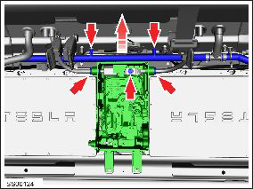
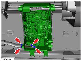
- Release the clips (x2) that secure the charger coolant hose to the heel board.
- Remove the bolts (x4) that secure the HV junction box (torque 5
Nm).
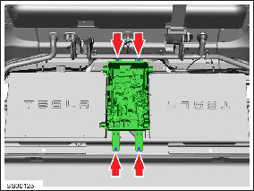
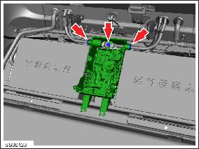
- Disconnect the junction box to slave charger connectors (x2). Note: Note installed position of components before removal. Note: Lower specification vehicles do not have this component installed.
- Disconnect the High Voltage Interlock (HVIL) loop connector and
position it aside.
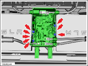
- Disconnect the junction box to master charger connectors (x5). Note: Note installed position of components before removal.
- Carefully lift the junction box and support it on a block to gain access to connectors.
- Remove the bolts (x2) that secure the positive and negative charge port cables at the HV junction box (torque 9 Nm).
- Release the quick connectors (x2) that secure the charge port
cables to the HV junction box body, then move the cables aside.
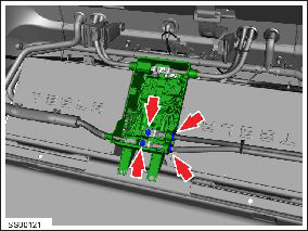
- Remove the bolts (x2) that secure the DCDC positive and negative cable terminals to the HV junction box (torque 9 Nm).
- Release the quick connectors (x2) that secure the DCDC cables to
the HV junction box body, then move the cables aside.
- Remove the bolt that secures the drive inverter and HV battery positive cables to the HV junction box (torque 9 Nm).
- Release the quick connectors (x2) that secure the drive inverter
and HV battery positive cables to the HV junction box body, then
move the cables aside.
- Remove the bolt that secures the drive inverter and HV battery negative cables to the HV junction box (torque 9 Nm).
- Release the quick connectors (x2) that secure the drive inverter and HV battery negative cables to the HV junction box body, then move the cables aside.
- Remove the bolt that secures the ground strap to the HV junction box (torque 5 Nm).
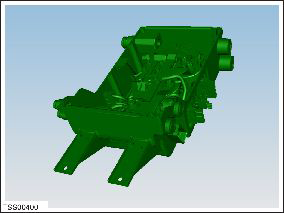
- Remove the HV junction box.
Installation procedure is the reverse of removal.
READ NEXT:
 HV Junction Box - Cover - 1st Generation (Remove and Replace)
Warning: Only technicians who have been trained in High
Voltage Awareness are permitted to perform this procedure. Proper
personal protective equipment (PPE) and insulating HV gloves with a
HV Junction Box - 2nd Generation (Remove and Replace)
Warning: Only technicians who have been trained in High
Voltage Awareness are permitted to perform this procedure. Proper
personal protective equipment (PPE) and insulating HV gloves with a
SEE MORE:
FCC and IC Certification
* The in-cabin radar is restricted to factory installation.
The devices listed above comply with Part 15 of the FCC rules and Industry
Canada's license-exempt RSS
Standard(s) and EU Directive 2014/53/EU.
Operation is subject to the following two conditions: (1) this device may not
cause harmfu
Coolant Heater - Electric - Battery - 2nd Generation (Remove and Replace)
Warning: Only technicians who have been trained in High
Voltage Awareness are permitted to perform this procedure. Proper
personal protective equipment (PPE) and insulating HV gloves with a
minimum rating of class 00 (500V) must be worn any time a high
voltage cable is handled. Refer
