Tesla Model S: Shaft - Steering Column - Intermediate Upper (Dual Motor) (Remove and Replace)
Warning: If the 12V power supply is disconnected, do not attempt to open any doors with door glass in closed position. Failure to follow this instruction could result in door glass shatter.
Note: Before disconnecting the 12V power supply, ensure that the driver's door window is fully open. Failure to follow this instruction could result in vehicle lockout.
Removal
- Remove the driver's side footwell cover:
- Left hand drive (LHD) vehicles: Refer to procedure
- Right hand drive (RHD) vehicles: Refer to procedure
- Disconnect 12V power (refer to procedure).
- Remove the wiper motor (refer to procedure).
- Remove the LH and RH shock tower to bulkhead struts (refer to procedure).
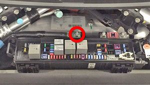
- Remove the fuse box cover.
- Remove the nut that secures 12V power supply for the DCDC
converter (torque 12.5 Nm).
- If the vehicle is equipped with air suspension, release the
screws (x2) that secure the air reservoir (torque 2.5 Nm). Carefully
set the reservoir in the RH side of the underhood area.
Note: It is not necessary to disconnect the air lines.
.png)
- Mark the lower intermediate shaft position relative to the upper intermediate shaft and pinion.
- Remove the nut and bolt that secure the lower intermediate shaft
to the upper intermediate shaft (torque 50 Nm).
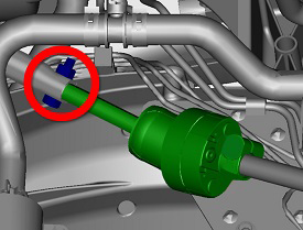
- Release the lower intermediate shaft from the slot in the upper intermediate shaft.
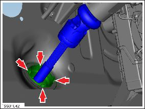
- From inside the vehicle, remove the bolt that secures the upper intermediate shaft to the column shaft (torque 30 Nm).
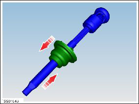
- Release the clips (x4) that secure the steering shaft seal to
the bulkhead.
- Remove the upper intermediate shaft.
Installation procedure is the reverse of removal, except for the following:
Caution: Replace all nylon-insert locknuts.
- Have an assistant ensure that the upper intermediate shaft to column marks align correctly.
- Connect a laptop with Toolbox 2.0 or later to the vehicle.
- In Toolbox, select Panels > Steering > Power Steering (EPAS) Control. Click the Start/Play button and follow the onscreen instructions.
Note: After calibrating EPAS, drive the vehicle for a minimum of 5 minutes before returning the vehicle to the customer.
READ NEXT:
 Steering Wheel (Remove and Replace)
Removal
Remove the driver's air bag (refer to procedure).
Position the wheels straight ahead. Mark the steering wheel
relative position to the column.
Remove and discard the bolt
Steering Column (Remove and Replace)
Removal
Ensure that the front road wheels are in a straight ahead
position.
Remove the driver's side lower dash trim (refer to procedure).
Remove the steering controller modul
SEE MORE:
Disconnect 12V Power (Dual Motor)
Warning: If the 12V power supply is disconnected, do
not attempt to open any doors with door glass in closed position.
Failure to follow this instruction could result in door glass
shatter.
Note: Before disconnecting the 12V power supply,
ensure that the driver's door window is
Bleed Procedure - System (Remove and Replace)
Warning: If the 12V
power supply is disconnected, do not attempt to open any doors
with door glass in closed position. Failure to follow this
instruction could result in door glass shatter.
Note: Before
disconnecting the 12V power supply, ensure that the driver's
door w
