Tesla Model S: Sway Bar - Front (Dual Motor) (Remove and Replace)
Warning: If the vehicle has air suspension, activate "Jack" mode on the touchscreen before raising and supporting the vehicle.
Warning: If the 12V power supply is disconnected, do not attempt to open any doors with door glass in closed position. Failure to follow this instruction could result in door glass shatter.
Note: Before disconnecting the 12V power supply, ensure that the driver's door window is fully open. Failure to follow this instruction could result in vehicle lockout.
Removal
- Position the vehicle on a lift, but do not raise it at this time.
- Remove the underhood storage unit (refer to procedure).
- Disconnect the first responder loop (X536) Do not cut the loop.
- Disconnect the 12V battery ground connection (torque 5 Nm).
- Release the bolts (x2) that secure the steering rack to the
subframe (torque 175 Nm).
.png)
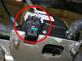
- Disconnect the harnesses (x3) from the power steering rack.
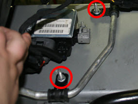
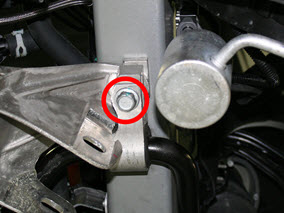
- On both sides of the vehicle, remove the bolt that secures the
steering brace to the subframe (torque 26 Nm).
.png)
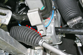
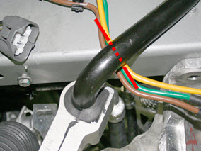
- On the RH side of the vehicle, release the fir tree clip that
secures the coolant hose to the steering brace.
.png)
- Disconnect the harness from coolant pumps 1 and 2, then remove both coolant pumps from the subframe. Note: It is not necessary to disconnect the coolant hoses from the pumps. Note: It is not necessary to remove the rubber isolators from the pumps.
- Raise the vehicle, then remove the front wheels (refer to procedure).
- On both sides of the vehicle, remove the lower front wheel arch liner (refer to procedure).
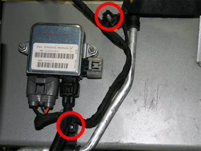
- On the RH side of the vehicle, remove the condenser fan (refer to procedure). Note: Only perform this step on the RH side of the vehicle.
- Remove the RH condenser fan control module (refer to procedure).
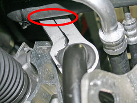
- On both sides of the vehicle, restrain the tie rod ball joint
pin, then remove the nut that secures the tie rod end to the knuckle
(torque 103 Nm).
Caution: To prevent ball joint damage, always hold the ball joint pin with a wrench while loosening or tightening the lock nut.
.png)
- Remove the front aero shield (refer to procedure).
- Remove the LH and RH front lower control arms (refer to procedure). Note: Do not remove the rear lower control arms.
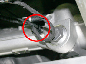
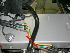
- Working from beneath the vehicle, remove the connector from the
base of the 3 way valve.
- Release the edge clip that secures the 3 way valve harness to
the subframe. Move the harness above the sway bar and out of the
working area.
- Note: This step is for air suspension vehicles only. Working from the RH wheelwell, remove the bracket that secures the air suspension lines to the side rail.
- Working in the LH wheelwell, release the cable ties (x2) that
secure the fan control module harness to the side rail.
- Remove the nuts (x2) that secure the A/C line to the side rail
(torque 5.5 Nm).
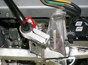
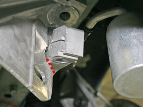
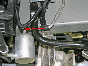
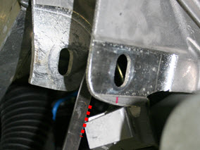
- On the RH side of the vehicle, loosen the bolt that secures the
steering brace to the base of the side rail (torque 26 Nm), then
remove the brace.
Note: Do not remove the bolt.
.png)
-
Note: This step is for air suspension vehicles only.
On the LH side of the vehicle, release the clip that secures the air
suspension line to the steering brace.
.png)
- Repeat step 22 to remove the LH steering brace.
- On both sides of the vehicle, remove and discard the bolt that
secures the sway bar to the sway bar end links (torque 70 Nm).
.png)
- On both sides of the vehicle, remove and discard the bolt that
secures the sway bar bracket to the base of the side rail (torque
115 Nm).
- Working from the RH wheelwell, rotate the sway bar forward.
Note: The bar rotates freely until the LH sway bar bracket is blocked by the subframe.
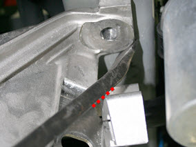
- Use a pry bar to provide clearance between the subframe and LH
sway bar bracket.
Caution: Do not damage the subframe.
- Continue rotating the sway bar forward. Ensure that:
- The sway bar does not damage the A/C line on the LH side
rail.
- Air suspension vehicles only: The sway
bar does not damage the air suspension lines on the RH side
rail.
- The sway bar does not damage the A/C line on the LH side
rail.
- On both sides of the vehicle, pivot the sway bar bracket over
the tie rod.
Caution: Do not damage the tie rod boot.
- Working from the RH wheelwell, push the sway bar inboard and
route it underneath the coolant hose.
- Working from the LH wheelwell, pull the sway bar outboard. Caution: Have an assistant stand beneath the center of the vehicle and guide the sway bar as it is removed to ensure that no harnesses or hoses are damaged.
- Maneuver the LH sway bar bracket so that it does not damage the
coolant hose, harness, or air suspension line (if equipped).
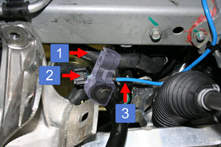
1 Coolant hose 2 Harness 3 Air suspension line - Completely remove the sway bar from the vehicle.
- Reinstall the front sway bar. Installation is the reverse of
removal, except for the following:
- During reinstallation, first pivot the LH sway bar bracket below the LH tie rod.
- Air suspension vehicles only: While
rotating the bracket back into its installation position,
ensure that the air suspension lines on both sides of the
vehicle are inboard of the the sway bar.
- If necessary, use a pry bar to move the RH side of the
sway bar underneath the subframe.
- Replace the nuts that secure the sway bar to the end links.
Caution: Do not damage the subframe or sway bar.
- Lower the vehicle to ride height.
- Fully torque the front control arms to the subframe (torque 130 Nm).
- Perform a four wheel alignment (refer to procedure).
READ NEXT:
 Control Arm - Upper - Front - LH (Remove and Replace)
Warning: If the vehicle has air suspension, activate "Jack"
mode on the touchscreen before raising and supporting the vehicle.
Removal
Position the vehicle in preparation for raising
Control Arm - Upper - Front - RH (Remove and Replace)
Warning: If the vehicle has air suspension,
activate "Jack" mode on the touchscreen before raising and
supporting the vehicle.
Note: Graphics show the LH side. The RH side is similar.
Link - Lower - Fore - LH (Remove and Replace)
Warning: If the vehicle has air suspension, activate "Jack"
mode on the touchscreen before raising and supporting the vehicle.
Removal
Loosen the front LH lug nuts.
Raise and
SEE MORE:
HV Junction Box - 1st Generation (Remove and Replace)
Warning: Only technicians who have been trained in High
Voltage Awareness are permitted to perform this procedure. Proper
personal protective equipment (PPE) and insulating HV gloves with a
minimum rating of class 00 (500V) must be worn any time a high
voltage cable is handled. Refer
Drop In Center Console Assembly (Remove and Replace)
Removal
Move the front seats to their rearmost positions to allow for
additional access.
Unplug the phone adaptor cable from the USB connector, if
installed.
Pull the two panels off from the sides of the center
