Tesla Model S: Air Suspension - Primary Lines Assembly (Remove and Replace)
Warning: To avoid personal injury, eye protection must be worn when performing this operation.
Removal
- Raise and support the vehicle (refer to procedure).
- Depressure the air suspension system (refer to procedure).
- Disconnect 12V power.
- Rear wheel drive (RWD): Refer to procedure.
- Dual Motor: Refer to procedure.
- Remove the underhood storage unit (refer to procedure).
- Remove the upper front RH wheel arch liner (refer to procedure).
- Remove the rear LH and RH wheel arch liners (refer to procedure).
- Remove the HV battery assembly (refer to procedure).
- Remove the rear subframe assembly (refer to procedure).
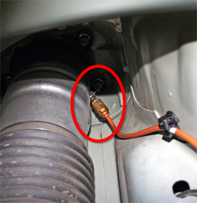
- Release the fitting from the rear left air spring (torque 5 Nm).
Caution: Plug the line connection to prevent ingress of moisture or dirt.
- Release the air line clips on the frame studs between the rear left and rear right air springs.
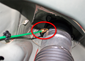
- Release the fitting from the rear right air spring (torque 5
Nm).
Caution: Plug the line connection to prevent ingress of moisture or dirt.
- Release the air line clips on the frame studs between the rear right and front right air springs.
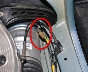
- Release the fitting from the front right air spring (torque 5
Nm).
Caution: Plug the line connection to prevent ingress of moisture or dirt.
- Release the air line clips between the front right air spring and the valve block.
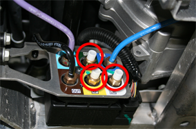
- Release the RR, LR, and FR fittings from the valve block (torque
3.5 Nm).
Caution: Plug the line connection to prevent ingress of moisture or dirt.
Installation procedure is the reverse of removal, except for the following:
- Install new fittings into the air springs and valve block
before installing the air lines.
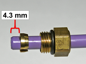
Note: Ensure that the collet is 4.3 mm from the end of the air line to prevent air pressure restriction.
READ NEXT:
 Air Line - Air Suspension - Reservoir to Compressor (Remove and Replace)
Removal
Raise and support the vehicle (refer to procedure).
Depressure the air suspension system (refer to procedure).
Disconnect 12V power.
Rear wheel drive (
Air Line - Air Suspension - Compressor to Valve Block (Remove and Replace)
Warning: To avoid personal injury, eye protection must be
worn when performing this operation.Removal
Raise and support the vehicle (refer to procedure).
Disconnect 12V power.
Air Line - Air Suspension - Valve Block Exhaust (Remove and Replace)
Removal
Raise and support the vehicle (refer to procedure).
Remove the underhood storage unit (refer to procedure).
Release the fitting from the valve block (torque 3.5 Nm).
SEE MORE:
Unable to charge - Mobile Connector GFCI tripped
Unplug charge handle from charge port and retry
The vehicle cannot charge because the ground-fault circuit interrupter (GFCI)
in the Mobile Connector has tripped.
Like the GFCI in a wall outlet, this feature is designed to stop the flow of
electricity when there is a problem. It has
interrupted
Brake Hose - Flexible - Front - LH (Remove and Replace)
Warning: If the vehicle
has air suspension, activate "Jack" mode on the touchscreen before
raising and supporting the vehicle.
Removal
Remove the front LH wheel
(refer to procedure).
Clean the areas that surround the connections
at each end of the brake h
