Tesla Model S: Casing - Transmitter - Remote Keyless Entry (RKE)
Tesla Model S (2012-2026) Service Manual / Electrical / Casing - Transmitter - Remote Keyless Entry (RKE)
Caution: Perform this procedure while using the proper anti-electrostatic discharge equipment. Refer to TN-14-92-003, "Electrostatic Discharge Tooling". Removal
- Remove the transmitter battery.
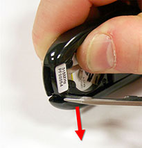
- Hold the transmitter in one hand. Place the blade of a flat
screwdriver or similar object on the edge of the side panel, then
press away from the transmitter to release the side panel.
- Repeat step 2 on the other side panel.
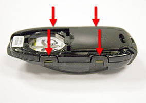
- Release the 4 clips, then remove the bottom panel.
- Remove and retain the circuit board. Caution: Take care not to damage component(s).
- Discard the other components.
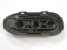
- Place the internal structure in the top panel.
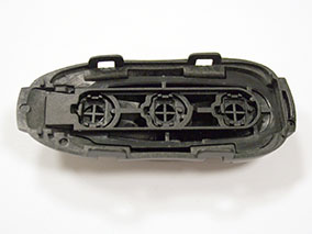
- Place the 3 buttons in the internal structure.
Note: Place the shortest button in the front hole, the tallest button in the middle hole, and the medium-length button in the rear hole.
Note: If a button does not sit flush with the internal structure, it is in the wrong position.
- Insert the circuit board with the buttons facing down. Caution: Take care not to damage component(s).
- Install the bottom cover.
- Install the side covers. Note: Position the tabs on the side cover in the notches at the top of the transmitter, then rotate the side cover into position.
- Install the battery.
READ NEXT:
 Transmitter - Remote Keyless Entry (RKE) - Programming
Key LearnCaution: Before beginning this procedure, it is necessary to
have all keys present. Any keys that are not present will deactivate
after completing the procedure.
Sit in the d
LF Antenna - Bumper Carrier (Remove and Replace)
Removal
Remove the underhood storage unit (refer to procedure)
Disconnect the LF antenna harness connector.
Working thr
LF Antenna - RH - A Post (Remove and Replace)
Warning: If the vehicle has air suspension, activate "Jack"
mode on the touchscreen before raising and supporting the vehicle.
Removal
Raise and support the vehicle (refer to pro
SEE MORE:
Exterior/Interior Overview
Exterior Overview
NOTE: Depending on market region, vehicle configuration, and options
purchased, your vehicle may look slightly different than described.
Exterior lights
Door handles
Charge port
Autopilot cameras
Exterior mirrors
Hood/Front trunk
Front/rear tow eye cover
Wheels and tir
Switch - Window Lift - Front Passenger's (Remove and Replace)
Removal
Remove passenger door trim. Removal of passenger door trim is
similar to driver's door (refer to procedure)
Move acoustic pad aside to access door trim.
Caution: Take care not to damage component(s).
© 2019-2026 Copyright www.tesms.org
