Tesla Model S: Charge Port - 3 Phase (Remove and Replace)
Note: This procedure describes how to remove and install the 3 phase charge port. If the vehicle is equipped with a single phase charge port, refer to procedure 44012202 (refer to procedure).
Warning: Only technicians who have been trained in High Voltage Awareness are permitted to perform this procedure. Proper personal protective equipment (PPE) and insulating HV gloves with a minimum rating of class 00 (500V) must be worn any time a high voltage cable is handled. Refer to Tech Note TN-15-92-003, "High Voltage Awareness Care Points" for additional safety information. Removal
- Open the charge port.
- Remove the LH trunk trim (refer to procedure).
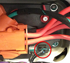
- Release the 12V harness connection from the charge port.
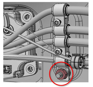
- Remove the grounding bracket by releasing the nut that secures
it to the body (torque 6 Nm).
- Disconnect the harness that connects the tail light to the
charge port.
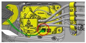
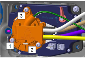
- Remove the cover from the cable connector by using a trim tool
or similar non-conductive tool to bend the 3 tabs that secure the
cover to the cable connector.
Note: The locations of the tabs are marked by arrows on the face of the cover.
Caution: Do not lose or damage the magnet on the outboard side of the cable connector.
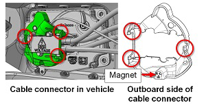
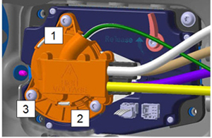
- Remove the 3 bolts that secure the cable connector to the charge
port in the order shown (torque 4 Nm). Remove the cable connector.
- Remove the LH taillight assembly (refer to procedure) .
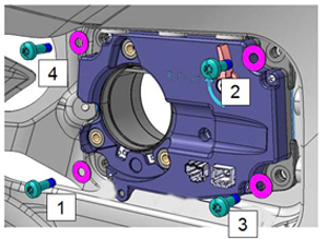
- Remove the bolts in the order shown (torque 3 Nm). Remove the
charge port.
Installation procedure is the reverse of removal, except for the following:
- When securing the charge port to the body, install all 4
bolts loosely, then tighten them in the order shown.
Note: Insert all 4 bolts loosely before tightening them in the proper sequence.
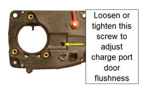
- Before installing the cable connector, close the charge port
door and verify that it is 0-2 mm underflush to the body. If
necessary, turn the screw to adjust the magnet that secures the
charge port door.
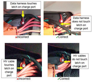
- When reinstalling the cable connector, ensure that the HV
cables and data harness do not touch or interfere with the latch
on the inside of the charge port.
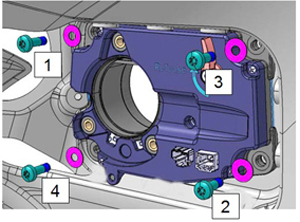
- When securing the cable connector to the charge port,
loosely install all 3 bolts, then tighten them in the order
shown.
Note: Insert all 3 bolts loosely before tightening
them in the proper sequence.
- After reinstalling all components, perform a firmware update.
READ NEXT:
 Release Cable
Note: This procedure describes how to manually release a
cable from the single phase charge port. If the vehicle is equipped
with a 3 phase charge port, refer to procedure 44013205 (refer to
Reinstall Components
Installation of components is reverse of removal, except for the
following:
When reconnecting the HV cables to the charge port:
Remove any adhesive patch residue from the mating surface
SEE MORE:
Control Arm - Upper - Front - RH (Remove and Replace)
Warning: If the vehicle has air suspension,
activate "Jack" mode on the touchscreen before raising and
supporting the vehicle.
Note: Graphics show the LH side. The RH side is similar.
Removal
Position the vehicle in preparation for raising it, but keep the
vehicle
Setup
Warning: Only technicians who have been trained in High
Voltage Awareness are permitted to perform this procedure. Proper
personal protective equipment (PPE) and insulating HV gloves with a
minimum rating of class 00 (500V) must be worn any time a high
voltage cable is handled. Refer
