Tesla Model S: HV Junction Box - Cover - 2nd Generation (Remove and Replace) - Installation
Tesla Model S (2012-2026) Service Manual / High Voltage System / HV Junction Box - Cover - 2nd Generation (Remove and Replace) / HV Junction Box - Cover - 2nd Generation (Remove and Replace) -
Installation
Installation
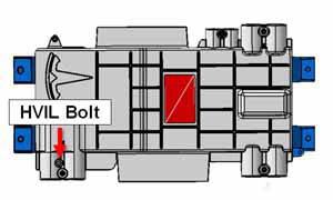
- Position the HVJB cover.
- Install the HVIL bolt loosely. Do not tighten it fully at this
time.
- North America, Japan
Note: In North American and Japanese vehicles, the HVIL bolt is one-time use only. Install a new bolt during reinstallation.
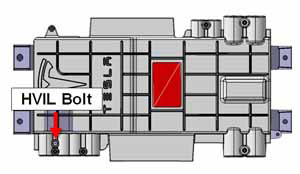
- Europe and APAC
Note: In European and APAC vehicles, the HVIL bolt can be reused during reinstallation.
- North America, Japan
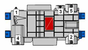
- Install the remaining fasteners that secure the HVJB cover in
the order shown.
- North America, Japan (torque 8 Nm)
Note: In North American and Japanese vehicles, there are 5 additional fasteners.
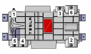
- Europe and APAC (torque 8 Nm)
Note: In European and APAC vehicles, there are 6 additional fasteners.
- North America, Japan (torque 8 Nm)
- Fully torque the HVIL bolt:
- North America and Japan: 4 Nm
- Europe and APAC: 5 Nm
READ NEXT:
 HV Junction Box - Reed Switch - 1st Generation (Remove and Replace)
Note: This procedure only applies to vehicles with the
1st generation High Voltage Junction Box.
Special tools required for this procedure:
Supplier
HV Rapid Mate Vehicle Side (Remove and Replace)
Removal
Remove the HV battery assembly(refer to procedure).
Lower the vehicle, but keep it in position to raise it in a
later step.
Remove the 2nd row seat cushion frame (refer to
HV Harness - HVJB to Charge Port - 2nd Generation
Warning: Only technicians who have been trained in High
Voltage Awareness are permitted to perform this procedure. Proper
personal protective equipment (PPE) and insulating HV gloves with a
SEE MORE:
Badge - Ludicrous Speed (Retrofit)
Special tool required for this procedure:
Supplier
Part Number
Description
Tesla
1054190-00-A
FEELER GAUGES
Procedure
Note: This procedure onl
Door - Charge Port - Non-Motorized (Remove and Replace)
Removal
Remove the LH tail light assembly (refer to procedure).
Remove the screws (x3) that secure the charge port door to the
tail light assembly.
Remove the charge port door.
Installation
© 2019-2026 Copyright www.tesms.org
