Tesla Model S: Module - Park Assist (Remove and Replace)
Tesla Model S (2012-2026) Service Manual / Electrical / Module - Park Assist (Remove and Replace)
Removal
- Remove the LH side rear trunk trim for access (refer to procedure).
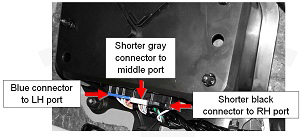
- Disconnect the harness connections (x3) from the module.
Caution: Mark the harnesses so that they are reinstalled properly.
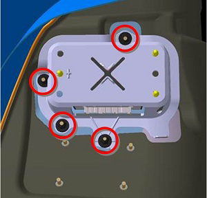
- Remove the nuts (x4) that secure the park assist module and
bracket to the body (torque 3 Nm).
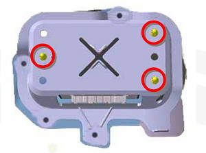
- Remove the park assist module from the bracket by releasing the
push rivets (x3).
Installation procedure is the reverse of removal, except for the following:
-
Use Toolbox to update or redeploy the firmware:
- If the vehicle is not running the latest firmware, run the "Vehicle Firmware Update" procedure.
- If the vehicle is running the latest firmware, run the "Firmware Redeploy" procedure.
- If the vehicle has only 8 park assist sensors in total, run the "Park Assist VIN Learn" procedure in Toolbox.
READ NEXT:
 Module - Electric Park Brake - EPB (Remove and Replace)
Removal
Remove the RH side trunk trim (refer to procedure).
Disconnect the harness connectors (x2) from the electric park
brake (EPB) module.
Module - Sunroof Controller (Remove and Replace)
Removal
Remove the body control module (BCM) (refer to procedure)
Remove the 4 bolts and 1 nut that secure the sunroof controller
mounting bracket to the body (torque 8 Nm).
Module - Sunroof Controller (RHD) (Remove and Replace)
Warning: If the 12V power supply is disconnected, do
not attempt to open any doors with door glass in closed position.
Failure to follow this instruction could result in door glass
shat
SEE MORE:
Brake Rotor - Rear - LH (Remove and Replace)
Warning: If the vehicle
has air suspension, activate "Jack" mode on the touchscreen before
raising and supporting the vehicle.
Special tool(s) required for this procedure:
Supplier
Part Number
Subframe Assembly - Rear (Remove and Install) - Removal
Note: Loosen suspension
fasteners by hand, then use a cordless electric drill with a 3/8
in drive adapter and a 3/8 in drive air ratchet wrench.
Warning: Only technicians
who have been trained in High Voltage Awareness are permitted to
perform this procedure. Proper personal pr
© 2019-2026 Copyright www.tesms.org
