Tesla Model S: North America and Japan only: Inspect the shield collar clamp
Tesla Model S (2012-2026) Service Manual / High Voltage System / HV Junction Box - Cover - 2nd Generation (Remove and Replace) / North America and Japan only: Inspect the shield collar clamp
- Insert the HVIL bolt into the shield collar clamp by 2 threads.
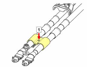
1 Install HVIL bolt 2 threads - With the HVIL bolt loosely installed, move the bolt from side to
side. Note whether there is any free play that might indicate
stripped threads in the shield collar clamp.
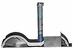
- If there is minimal free play, the shield collar clamp does
not need to be replaced. Skip to the Installation section of
this procedure.
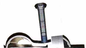
- If there is significant free play, the shield collar clamp
needs to be replaced. Continue to the next step.
- If there is minimal free play, the shield collar clamp does
not need to be replaced. Skip to the Installation section of
this procedure.
- Inside the HVJB, mark the 2 wires that lead to the charge port as B+ and B-. Caution: Do not reverse the polarity of the cables during reinstallation.
- Inside the HVJB, unbolt the 2 cables that lead to the charge port (torque 9 Nm). Note: It is not necessary to replace the fastener(s) after it is removed. The threaded area has a reusable dry sealant, which looks similar to adhesive patch material.
- Cut the cable ties that secure shield collar clamp
- Replace the shield collar clamp.
- Inside the HVJB, secure the HV cables that lead to the charge port.
- Replace the cable ties that secure the HV cables.
READ NEXT:
 HV Junction Box - Cover - 2nd Generation (Remove and Replace) -
Installation
HV Junction Box - Cover - 2nd Generation (Remove and Replace) -
Installation
Installation
Position the HVJB cover.
Install the HVIL bolt loosely. Do not tighten it fully at this
time.
North America, Japan
Note: In North American a
HV Junction Box - Reed Switch - 1st Generation (Remove and Replace)
Note: This procedure only applies to vehicles with the
1st generation High Voltage Junction Box.
Special tools required for this procedure:
Supplier
HV Rapid Mate Vehicle Side (Remove and Replace)
Removal
Remove the HV battery assembly(refer to procedure).
Lower the vehicle, but keep it in position to raise it in a
later step.
Remove the 2nd row seat cushion frame (refer to
SEE MORE:
Handle - Exterior Release - Door - Front - LH (Remove and Replace)
Removal
Remove regulator assembly (refer to procedure)
Make sure exterior release handle is fully retracted.
Disconnect handle harness connector.
Remove nuts (x4) securing door release assembly to reinforcement
(torque 9 Nm).
Carefully release door handle assembly from d
Standby Mode
To keep Model S ready to Summon and reduce the time
it takes to warm up, turn on Standby Mode. Touch
Controls > Autopilot > Standby Mode. When Standby
Mode is turned on, you can conserve Battery energy by
disabling Standby Mode at these locations:
Exclude Home - Disables Standby Mode at
© 2019-2026 Copyright www.tesms.org
