Tesla Model S: Ride Height - Adjust
Tesla Model S (2012-2026) Service Manual / Suspension / Ride Height - Adjust
Special tool required for this procedure:
| Supplier | Part Number | Description |
| Tesla | 1049633-00-A | Ride Height Measuring Tool |
- Use Toolbox to verify that the "Wheel Type" vehicle configuration variable is correct. If necessary, change the vehicle configuration. Note: Changing the "Wheel Type" configuration variable affects the target calibration height.
- Position the vehicle on a flat, level surface that has adequate workspace on the sides of the vehicle.
- Adjust the tire pressures to the recommended values. In this manual, refer to General Information > Technical Data > Tire Pressures.
- Remove heavy objects from the vehicle.
- Ensure that the steering wheel is centered.
- Ensure that there are no people in the vehicle.
- Calibrate the ride height measuring tool:
- Measure the overall height of the measuring end of the tool.
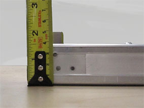
- Adjust the tool to compensate for the measured height.
Tighten the knob to secure the adjuster.
- Measure the overall height of the measuring end of the tool.
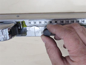
- Run the Toolbox "Air Suspension Calibration" procedure. When
prompted, measure as shown:
.png)
.png)
- Confirm proper system functionality by selecting a different ride height from the center display.
- If equipped, calibrate the front radar sensor (refer to procedure).
READ NEXT:
 Suspension - Front - Check Torque
Remove the front wheels (refer to procedure).
Check the tightening torque of the following fasteners on both sides of the
vehicle:
Tie rod end to the knuckle (torque 103 Nm).
Cau
Knuckle - Suspension - Front - LH (Remove and Replace)
Warning: If the vehicle has air suspension, activate "Jack"
mode on the touchscreen before raising and supporting the vehicle.
Removal
Remove the front hub (refer to procedure).
Hub - Front - LH (Remove and Replace)
Special tool(s) required for this procedure:
Supplier
Part Number
Description
Tesla
1062500-00-A
Magnetic F
SEE MORE:
Auto Opening and Closing
To operate a HomeLink device without using the
touchscreen, you can automate the device to open as
you approach, and close as you drive away:
1. Touch the HomeLink icon at the top of the Controls
screen, then choose the device you want to
automate.
2. Select the Auto-open when arriving checkbox
Cannot charge - Poor grid power quality possible
Retry / Try other charge location or Supercharging
Charging has stopped due to a condition that prevents your vehicle from
charging with AC power. DC fast charging /
Supercharging should still function as expected.
This condition could occur due to power supply disturbances caused by the
externa
© 2019-2026 Copyright www.tesms.org
