Tesla Model S: Subframe Assembly - Front (Remove and Install)
Special tools required for this procedure:
| Supplier | Part Number | Description |
| Tesla | 1021241-00-B | Subframe Fixture, Rear, MDLS |
| Tesla | 1021242-00-C | Subframe Fixture, Front Jig - MDLS |
Removal
- Vehicles with Air Suspension: Depressurize the air suspension (refer to procedure).
- Loosen the lug nuts for the front wheels.
- Remove the HV battery (refer to procedure).
- Remove the front skid plate (refer to procedure).
-
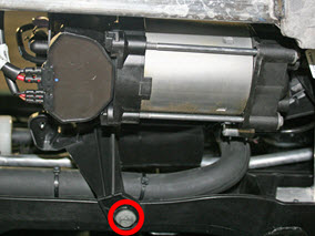
Release the bolt that secures the air
compressor bracket to the front carrier (torque 5.5 Nm).
Note: The remaining 2 bolts that secure the bracket are removed in a later step.
-
If equipped: On
each side of the vehicle, release the bolts (x2) that secure the
staybar (torque 11 Nm).
-
Rear wheel drive vehicles
only: Remove the nuts (x4) that secure the A/C compressor
bracket to the subframe (torque 8 Nm).
-
Remove the bolts (x2) that secure the chiller
to the subframe (torque 12 Nm).
-
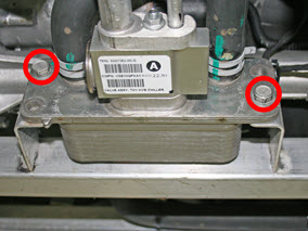
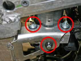
Remove the nuts (x2), washers (x2), and rubber
grommet that secure the ABS pump (torque 9 Nm).
-
Release the front bolt that secures the
radiator bypass 3-way coolant valve to the subframe (torque 5 Nm).
Note: The remaining
bolt that secures the 3-way valve is removed in a later
step.
- Disconnect the harness connector from each 3-way valve.
-
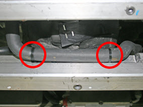
Dual motor vehicles only:
Release the clips (x2) that secure the coolant hose to the
subframe.
- Release the A/C drain hose from the subframe.
- Remove the front wheels (refer to procedure).
- Fully lower the vehicle.
- Slide coolant pumps 1 and 2 off of the subframe brackets.
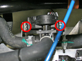
-
Release the remaining bolts (x2) that secure
the chiller bypass 3-way valve to the subframe (torque 5 Nm).
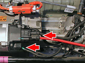
-
Disconnect the 2 harnesses from the steering
rack.
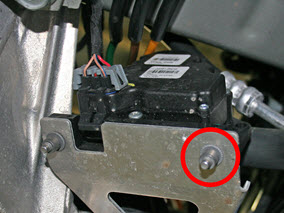
- Release the bolts (x2) that secure the air compressor bracket to the subframe (torque 6 Nm).
- Release the remaining bolt that secures the radiator bypass 3-way valve (torque 5 Nm).
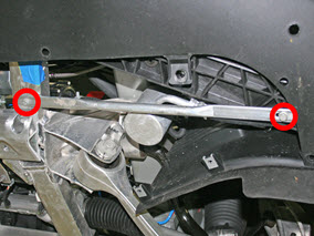
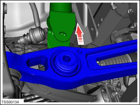
-
On each side of the vehicle, release the bolt
that secures the steering brace to the subframe (torque 26 Nm):
-
RWD vehicles:
-
Dual motor vehicles:
.png)
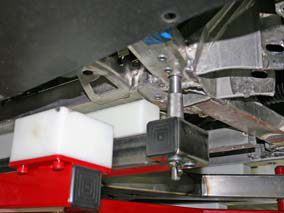
Place a metal rod or similar across the top of the front frame rails.
-
RWD vehicles:
-
Use tie-down cords to support the following
components:
- Air compressor, if equipped
- ABS pump
- Coolant pump 1
- Coolant pump 2
- Radiator bypass 3-way valve
- Chiller bypass 3-way valve
- Raise the vehicle to access the wheelwells.
- On both sides of the vehicle, pull the rear arch liners forward.
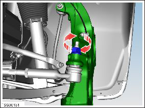
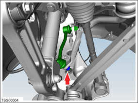
-
On both sides of the vehicle, restrain the tie
rod ball joint pin, then remove the nut that secures the tie rod end
to the knuckle (torque 103 Nm).
Caution: To prevent ball joint damage, always hold the ball joint pin with a wrench while loosening or tightening the lock nut.
- Fully raise the vehicle.
-
Remove the bolt and nut that secure the front
shock absorber to the rear lower control arm (torque 140 Nm).
-
Release the shock absorber from the lower arm.
-
On each side of the vehicle, remove and discard
the nut that secures the sway bar to the sway bar end links (torque
70 Nm).
Caution: Replace all nylon-insert locknuts.
- On each side of the vehicle, mark a witness line on the subframe cam to aid installation, then remove the bolts that secure the front and rear lower control arms to the subframe (torque 130 Nm).
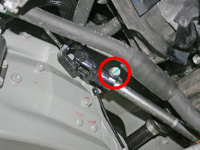
-
Remove the bolt that secures the lower
intermediate shaft to the steering rack (torque 49 Nm).
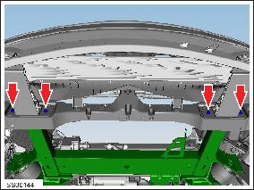
-
Remove the bolts (x4) that secure the front
subframe to the bumper carrier:
- Composite carrier: 7.5 Nm
- Magnesium carrier: 11 Nm
-
On each side of the vehicle, release the bolt
that secures the steering brace to the subframe (torque 26 Nm):
-
RWD vehicles:
-
Dual motor vehicles:
-
RWD vehicles:
- Raise the vehicle.
- Install the front subframe jig onto the subframe fixture.
-
Install the locating pins in the appropriate
location.
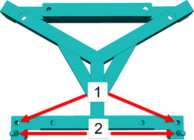
1 Rear wheel drive 2 Dual motor -
Have an assistant lower the vehicle. Guide the
front subframe onto the fixture.
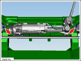
-
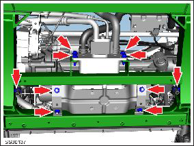
On each side of the vehicle, remove the 2 bolts
that secure the subframe to the chassis:
-
RWD:
- Forward bolt (torque 140 Nm)
- Rear bolt (Torque 76 Nm)
-
Dual Motor:
- Forward bolt (torque 115 Nm)
- Rear bolt (Torque 115 Nm)
-
RWD:
- Raise the vehicle.
Installation procedure is the reverse of removal, except for the following: Warning: Only use cleaning agents and solvents in a well-ventilated area. Caution: Replace all nylon-insert locknuts. Note: Clean the affected areas before installation.
- Ensure that all subframe fixing bolts are started before attempting to tighten.
- Align the witness marks on the chassis and subframe.
- Align the suspension components to the subframe and set the cams to the previously marked positions. Do not fully tighten at this time.
- Remove the suspension from "Jack" mode and set to "Standard" and allow the suspension to settle.
- Transfer the vehicle to a 4 post lift (refer to procedure).
- Perform a 4-wheel alignment (refer to procedure) and fully torque all suspension components at ride height.
READ NEXT:
 Subframe Assembly - Front (Remove and Replace)
Removal
Remove front subframe assembly for access
(refer to procedure)
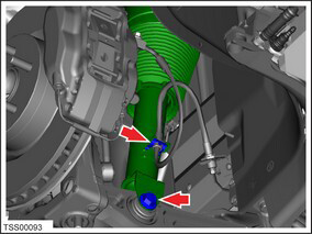
Remove and discard the bolts (x2) securing
steering rack assembly to subframe (torque 175 Nm).
Skidplate - Front (Remove and Replace)
Warning: If the vehicle
has air suspension, activate "Jack" mode on the touchscreen before
raising and supporting the vehicle.
Removal
Remove front aero shield
(refer
Skidplate - Rear (Remove and Replace)
Removal
Remove rear diffuser tray
(refer to procedure)
Remove screws (x2) securing rear skid plate to
subframe (torque 10 Nm).
In
SEE MORE:
Special Tools - HV Battery Alignment Rods
The HV battery alignment rods assist in aligning the HV battery during
installation.
Note: This tool is intended to be used by 2 technicians.
To use the alignment rods:
Position the table under the vehicle until the bolt holes in the battery
and vehicle are roughly aligned. Do not lo
Vent - Motorized - Front Fascia - LH (Remove and Replace)
Removal
If the vehicle is equipped with 1st generation front fascia
applique, remove front fascia applique (refer to procedure) .
Remove ankle catcher foam, if equipped.
Disconnect motorized vent harness connector.
