Tesla Model S: Target Calibration - Forward Facing Camera
Tesla Model S (2012-2026) Service Manual / Infotainment / Target Calibration - Forward Facing Camera
Special tool required for this procedure:
| Supplier | Part Number | Description |
| Tesla | 1053066-00-A | Camera Calibration Target |
Note: This procedure describes how to calibrate the forward facing camera. It does not apply to the rear facing camera.
- Ensure that the vehicle is running firmware version 6.2 or later.
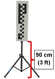
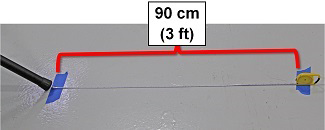
- Park the vehicle on a flat surface with at least 90 cm (3 ft) of space in front of the front fascia. Note: If the vehicle has air suspension, ensure that the suspension is level and set to "Standard".
- Set up the target tripod so that the bottom of the target is 90 cm (3 ft)
from the ground.
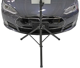
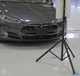
- Place the target in the appropriate starting position (this is "Location
1" in the Toolbox procedure):
- The checkered portion of the target is facing towards the vehicle
- The target is centered with the Tesla "T" on the front fascia
- The target has 2 legs under the front of the vehicle and both are less than 5 mm from the chin spoiler
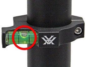
- Ensure that the target is on flat ground by examining the bubble level
on the back of the target.
- Apply a piece of tape on the ground behind the tripod leg that is
farthest from the vehicle.
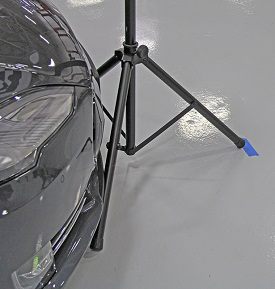
- Apply another piece of tape 90 cm (3 ft) behind the tape that was
applied in the previous step. This is "Location 2" in the Toolbox procedure.
Note: Do not move the target to Location 2 at this point.
- Connect a laptop with Toolbox 2.0 or later to the vehicle.
- In Toolbox, select Panels > Driver Assist > Camera Single Pole Target Auto Calibration.
- Click the Start/Play button.
- Follow the onscreen instructions to calibrate the forward facing camera.
Note: When prompted, move the target from "Location 1" to "Location 2".
Location 1 Location 2 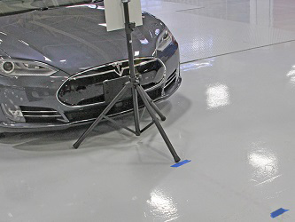
- Once the calibration procedure is completed, click Finish.
READ NEXT:
 Speaker - Front Door Premium Audio - LH/RH (Remove and Replace)
Removal
Remove door trim panel (refer to procedure)
Remove 4 screws securing speaker to spacer ring (torque 1.8 Nm).
Remove connector from door speaker.
Remove front door spea
Speaker - Rear Door All, Front Door Base Audio (Remove and Replace)
Removal
Remove rear door trim panel (refer to procedure)
Disconnect speaker harness connector.
Note: Components have been removed in this graphic
to aid cl
Subwoofer Assembly (Remove and Replace)
Removal
Remove RH side trunk trim (refer to procedure)
Remove screws (x3) securing subwoofer enclosure to body (torque
7 Nm).
SEE MORE:
Compressor (Dual Motor) (Remove and Replace)
Warning: Only technicians who have been trained in High
Voltage Awareness are permitted to perform this procedure. Proper
personal protective equipment (PPE) and insulating HV gloves with a
minimum rating of class 00 (500V) must be worn any time a high
voltage cable is handled. Refer
Finisher - Liftgate - Rear Window - Side - LH (Remove and Replace)
Removal
Remove the upper rear window finisher (refer to procedure).
Release the clips (x3) and remove the tailgate side finisher.
Caution: Take care not to damage component(s).
Note: Components have been removed in this graphic
to aid clarity.
© 2019-2026 Copyright www.tesms.org
