Tesla Model S: Actuator - Mode (Remove and Replace)
Tesla Model S (2012-2026) Service Manual / Thermal Management / Actuator - Mode (Remove and Replace)
Removal
- Remove IP carrier (refer to procedure)
- Disconnect duct temperature sensor harness connector.
- Remove screw securing duct to HVAC assembly and position duct
aside (torque 1 Nm).
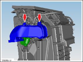
- Disconnect actuator harness connector.
- Remove screws (x3) securing mode actuator to HVAC assembly (torque 1 Nm).
- Note installed position of secondary flap link prior to removal.
- Remove air distribution mode flap actuator.
Caution: Take care not to damage component(s).
- Installation procedure is the reverse of removal, except for the following:
- Ensure secondary flap link is in correct position prior to installing actuator.
READ NEXT:
 Actuator - Front Passenger's Temperature (Remove and Replace)
Removal
Remove glove box assembly (refer to procedure)
Disconnect duct temperature sensor harness connector.
Remove screw securing duct to HVAC assembly, release from spigot
and p
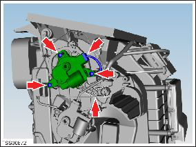
Actuator - Defrost (Remove and Replace)
Removal
Remove glove box assembly (refer to procedure)
Disconnect actuator harness connector.
Remove screws (x3) securing defrost door actuator to HVAC
assembly (torque 1 Nm).
Motor - Fan assembly - HVAC (Remove and Replace)
Removal
Power the passenger seat fully rearward for access.
Remove the passenger footwell closing trim (refer to procedure).
Disconnect the fan harness connector and position the
SEE MORE:
Panel - Aero Shield - Front (Remove and Replace)
Warning: If the vehicle has air suspension, activate "Jack"
mode on the touchscreen before raising and supporting the vehicle.
Removal
Raise and support the vehicle (refer to procedure).
Warning: Do not work on an incorrectly supported
vehicle.
Sensor - Impact - B Pillar (Remove and Replace)
Removal
Remove the B-pillar lower trim (refer to procedure).
Disconnect the impact sensor harness connector.
Remove the bolt that secures the impact sensor to the B-pillar
(torque 8 Nm).
Caution: The bolt is left-hand threaded / reverse
threaded.
© 2019-2026 Copyright www.tesms.org
