Tesla Model S: Applique - Fascia - Front - 2nd Generation (Remove and Install)
Tesla Model S (2012-2026) Service Manual / Body / Applique - Fascia - Front - 2nd Generation (Remove and Install)
Note: This procedure describes how to remove and install the 2nd generation front fascia applique. If the vehicle is equipped with a 1st generation front fascia applique, refer to procedure 10011402 (refer to procedure).
Removal
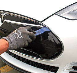
- Use a trim tool to release the front fascia applique.
Caution: Take care not to damage component(s).
- If installed, disconnect the parking sensor connectors (x2).
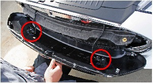
- If applicable, connect the parking sensor connectors (x2).
- Line up the clips (x7) on the front fascia applique with the corresponding holes in the front fascia bright carrier.
- Press both sides of the front fascia applique towards the front fascia bright carrier to engage the clips.
- Apply pressure around the perimeter of the entire front fascia applique to ensure that all of the clips are secure.
READ NEXT:
 Applique - Fascia - Front - 2nd Generation (Remove and Replace)
Note: This procedure describes how to remove and replace
the 2nd generation front fascia applique. If the vehicle is equipped
with a 1st generation front fascia applique, refer to procedure
Grill - Fascia - Front (Remove and Replace)
Removal
Vehicles with 1st generation front fascia applique only:
Remove the front fascia applique refer to procedure.
Vehicles with 2nd generation front fascia applique only:
Remo
Chin Spoiler Assembly (Remove and Replace)
Warning: If the vehicle has air suspension, activate "Jack"
mode on the touchscreen before raising and supporting the vehicle.
Removal
Remove the front fascia refer to procedure.
SEE MORE:
Battery - Auxiliary - 12V (Dual Motor) (Remove and Replace)
Warning: If the 12V power supply is disconnected, do
not attempt to open any doors with door glass in closed position.
Failure to follow this instruction could result in door glass
shatter.
Note: Before disconnecting the 12V power supply,
ensure that the driver's door window
To Use Traffic-Aware Cruise Control
To initiate Traffic-Aware Cruise Control when no vehicle
is detected ahead of you, you must be driving at least
18 mph (30 km/h), unless certain vehicle and
environmental conditions are met, in which case, you
may be able to initiate it at lower speeds. If a vehicle is detected ahead of
you, yo
© 2019-2026 Copyright www.tesms.org
