Tesla Model S: Bumper Assembly - Front (Remove and Replace)
Warning: If the 12V power supply is disconnected, do not attempt to open any doors with door glass in closed position. Failure to follow this instruction could result in door glass shatter.
Note: Before disconnecting the 12V power supply, ensure that the driver's door window is fully open. Failure to follow this instruction could result in vehicle lockout.
Removal
- Disconnect 12V power.
- Rear wheel drive (RWD): Refer to procedure.
- Dual Motor: Refer to procedure.
- Remove the front fascia assembly for access (refer to procedure).
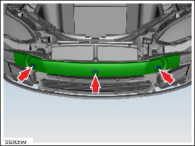
- If installed, remove the plastic rivets (x3) that secure the
knee support foam to the front bumper. Remove the knee support foam.
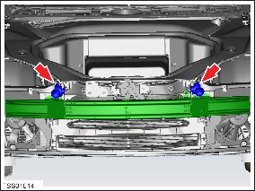
- If equipped, remove the bolts (x4) that secure both horn
brackets to the bumper carrier and tie the horns aside (torque 11
Nm).
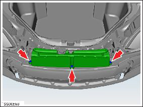
- Remove the plastic rivets (x3) that secure the foam to the front
bumper. Remove the bumper foam, if installed.
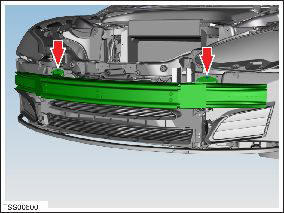
- Remove the bolts (x2) that secure the bumper to the carrier
(torque 11 Nm).
- Disconnect the harness connectors (x2) from the LH fan control module.
- Remove the nuts (x2) that secure the LH fan control module to
the chassis rail (torque 8 Nm).
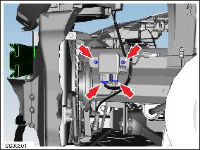
- Remove the LH fan control module.
- Repeat the previous 3 steps to remove the RH fan control module.
- Remove the bolts (x8) that secure the bumper to the crash
structure (torque 60 Nm).
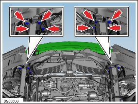
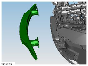
- Remove the front bumper.
Installation procedure is the reverse of removal.
READ NEXT:
 Ankle Catcher Assembly (Remove and Replace)
Removal
Remove the front fascia (refer to procedure).
Remove the bolts (x2) that secure the center of the ankle
catcher to the front ducting (torque 4 Nm).
Applique - Fascia - Front - 1st Generation (Remove and Replace)
Note: This procedure describes how to remove and replace
the 1st generation front fascia applique. If the vehicle is equipped
with a 2nd generation front fascia applique, refer to procedure
Applique - Fascia - Front - 2nd Generation (Remove and Install)
Note: This procedure describes how to remove and
install the 2nd generation front fascia applique. If the vehicle is
equipped with a 1st generation front fascia applique, refer to
procedur
SEE MORE:
Starting/Discharging the System
Starting the System
Press the emergency stop button to disable HV systems.
Pull out the display/keyboard/trackpad tray.
Press the red power button to turn on the on-board PC.
Follow the onscreen instructions to log in to the system.
Userna
Lamp - Reflex - Rear - LH (Remove and Replace)
Removal
Remove rear fascia assembly for access (refer to procedure)
Release clips (x2) securing reflex lamp to rear fascia.
Remove reflex lamp.
Installation
Installation procedure is the reverse of
