Tesla Model S: Installation, Configuration, and Coolant Purge
Tesla Model S (2012-2026) Service Manual / High Voltage System / Master Charger - RH - 2nd Generation (Remove and Replace) / Installation, Configuration, and Coolant Purge
Fully clean the area before installing the new charger.
Note: Have an assistant hold up the front of the HVJB 20-30 mm until the coolant hoses have been secured to the charger.
- Position the new charger over the mounting studs on the base of the vehicle, but do not secure the nuts at this time.
- Secure the coolant hoses to the new charger and resecure the locking rings.
- Remove the clamps from the coolant hoses.
- Install the 4 nuts that secure the charger to the body (torque 7 Nm).
- Secure the ground strap to the rear of the charger (torque 7 Nm). Note: Do not reconnect the outboard (low voltage) harnesses to the charger yet.
- If any HV cable terminals have contacted coolant, clean them with alcohol.
- Resecure all HV cables inside the HVJB:
- The 2 cables to the front drive unit (if equipped)
- The 4 HV cables to the HV battery and drive inverter
- The 2 HV cables to the DCDC converter
- The 4 HV cables to the charge port
- Reconnect the 2 HVJB harness connections to the master charger. If the vehicle is equipped with a slave charger, reconnect the 2 harnesses connections that lead from the HVJB to the slave charger.
- Reinstall the 4 bolts that secure the HVJB (torque 5 Nm).
- Reinstall the HVIL bolt, standard bolt, and 5 nuts that secure the HVJB cover (torque 5 Nm). Note: The HVIL bolt is a specific length in order to activate the HVIL switch. Ensure that the correct bolt is used during reinstallation.
- Connect the harnesses (x2) to the side of the master charger in
the following order:
Caution: Connecting harnesses in the wrong order
triggers multiple high-priority alerts.
- Connect the 10-pin harness to the rear port.
- Connect the 12-pin harness to the front port.
- If the vehicle is equipped with a slave charger, disconnect the
connectors (x2) from the side of the slave charger in the following
order:
Caution: Disconnecting harnesses in the wrong order
triggers multiple high-priority alerts.
- Disconnect the 12-pin harness from the rear port.
- Disconnect the 10-pin HVIL loopback connector from the front port.
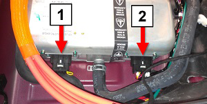
1 10-pin HVIL loopback connector 2 12-pin harness - Use the Toolbox "Charger Config" panel to configure the master charger:
- Use the Toolbox "Coolant Air Purge" to purge the coolant system. Monitor the coolant level in the reservoir and fill it as needed. Ensure that there are no coolant leaks in the area around the charger.
- Use Toolbox to update or redeploy the firmware:
Note:
- If the vehicle is not running the latest firmware, run the "Vehicle Firmware Update" procedure.
- If the vehicle is running the latest firmware, run the "Firmware Redeploy" procedure.
- Reinstall all components that were removed for access.
- Reconnect HV power.
- Disconnect the 12V float charger.
- If possible, charge the vehicle at above 40 A for several minutes and verify that there are no alerts.
READ NEXT:
 DCDC Converter - 1st Generation (Remove and Replace)
Warning: Only technicians who have been trained in High
Voltage Awareness are permitted to perform this procedure. Proper
personal protective equipment (PPE) and insulating HV gloves with a
DCDC Converter - 2nd Generation (Remove and Replace)
Warning: Only technicians who have been trained in High
Voltage Awareness are permitted to perform this procedure. Proper
personal protective equipment (PPE) and insulating HV gloves with a
DCDC Converter (Dual Motor) (Remove and Replace)
Warning: Only technicians who have been
trained in High Voltage Awareness are permitted to perform this
procedure. Proper personal protective equipment (PPE) and insulating
HV gloves with
SEE MORE:
Press Sensor - Door - Exterior Handle - Front - LH (Remove and Replace)
Removal
Remove door handle for access (refer to procedure)
Position handle assembly on a soft working surface.
Remove door handle rear seal.
Remove cable ties securing door pressure sensor and motor
wiring.
Release motor harness connector.
Remove press sensor screw.
Module - Seat Heater - Driver's Seat (Remove and Replace)
Removal
Open door.
Power seat height adjust fully upwards for access.
Disconnect seat heater module connectors and harnesses (x2).
Release clip securing seat heater module to seat.
Remove seat heater module.
© 2019-2026 Copyright www.tesms.org
