Tesla Model S: Powertrain Coolant Pump 1 (Dual Motor) (Remove and Replace)
Tesla Model S (2012-2026) Service Manual / Thermal Management / Powertrain Coolant Pump 1 (Dual Motor) (Remove and Replace)
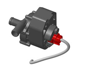
Coolant pump locations:
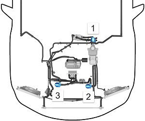
RWD Model S
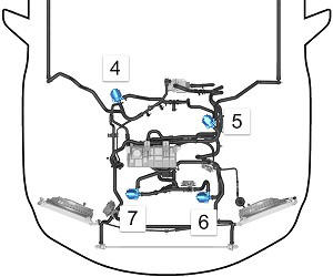
Dual Motor Model S
| 1 | Powertrain coolant pump 1 | RWD vehicle |
| 2 | Battery coolant pump 2 | RWD vehicle |
| 3 | Battery coolant pump 1 | RWD vehicle |
| 4 | Powertrain coolant pump 2 | Dual Motor vehicle |
| 5 | Powertrain coolant pump 1 | Dual Motor vehicle |
| 6 | Battery coolant pump 2 | Dual Motor vehicle |
| 7 | Battery coolant pump 1 | Dual Motor vehicle |
- Disconnect 12V and HV power (refer to procedure).
- Remove the wiper arms (refer to procedure).
- Remove the cowl panel (refer to procedure).
- Remove the LH shock tower to bulkhead strut (refer to procedure).
- Slide the pump off of the bracket.
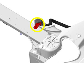
- Release the bolt that secures the bracket to the front shock tower crossmember (torque 6.5 Nm). Remove the bracket from the vehicle to provide additional access.
- Place absorbent material beneath the pump.
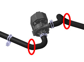
- Clamp and release the 2 hoses.
- Disconnect the electrical connector from the rear of the pump.
- Remove the pump from the vehicle.
Installation procedure is the reverse of removal, except for the following:
- Clean any spilled coolant.
- When all components have been reinstalled, refill and bleed the cooling system (refer to procedure).
READ NEXT:
 Powertrain Coolant Pump 2 (Remove and Replace)
Coolant pump locations:
RWD Model S
Dual Motor Model S
1
Powertrain coolant pump 1
RWD vehicle
2
Battery
Active Louver - Center (Remove and Replace)
Removal
Remove the front bumper (refer to procedure).
Remove the radiator (refer to procedure).
Remove the ankle catcher (refer to procedure).
Remove the plastic rivets (x3) that
Duct - Condenser LH (Remove and Replace)
Removal
Remove the front fascia assembly (refer to procedure).
Remove the bolts (x4) that secure the duct to the condenser
housing (torque 16 Nm on vehicles equipped with a magnesium
SEE MORE:
Wheel Arch Liner - Rear - LH (Remove and Replace)
Warning: If the vehicle has air suspension, activate "Jack"
mode on the touchscreen before raising and supporting the vehicle.
Removal
Raise and support the vehicle (refer to procedure)
Remove road wheel (refer to procedure)
Remove bolts (x2), plastic rivets (x2) securi
Wheel Sensor - TPMS (Remove and Replace) - Installation
Installation
Clean and inspect the wheel and valve hole.
Remove any dirt, burrs, or swarf.
Install the valve retaining screw to the wheel
sensor.
Note: Ensure that
the square faces are parallel with the slot in the sensor.
© 2019-2026 Copyright www.tesms.org
