Tesla Model S: Setup
Warning: Only technicians who have been trained in High Voltage Awareness are permitted to perform this procedure. Proper personal protective equipment (PPE) and insulating HV gloves with a minimum rating of class 00 (500V) must be worn any time a high voltage cable is handled. Refer to Tech Note TN-15-92-003, "High Voltage Awareness Care Points" for additional safety information.
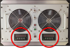
These instructions are for the 4th generation battery charger/discharger tool. The 4th generation tool has the following features:
- The serial number includes "G4"
- The charger/discharger tool has a rectangular load bank connector
- The load bank has a display below each fan
Setup
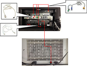
- Connect the high voltage components to the charger/discharger
tool, using the included harnesses.
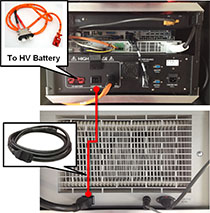
Warning: Cover the charger/discharger tool load bank connector with its protective flap when the HV cable is not installed.
Note: Hot air is exhausted from the rear of the discharger box when the battery is discharging. Position the cables away from the vents on the rear of the discharger to prevent them from being overheated.
- Connect the components to the wall outlet, using the included
power cables.
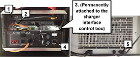
- Connect the signal and communication components, using the
included cables. Some cables might already be connected.
Note: The DB9-RJ45 Ethernet cable should be connected to the "IN" port on the power supply.
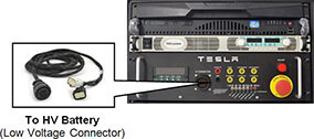
- Connect the low voltage (LV) connector to the battery, using the
included harness.
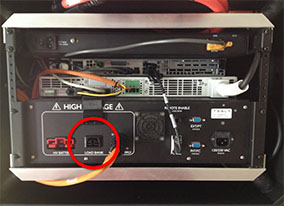
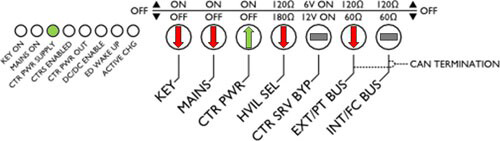
- Set the front panel control switches to the indicated positions.
READ NEXT:
 Starting/Discharging the System
Starting the System
Press the emergency stop button to disable HV systems.
Pull out the display/keyboard/trackpad tray.
Press the red power button to turn on the on-board PC.
Follo
Charging the Battery
Select Manual Mode from the Charge/Discharge Mode menu.
Type the desired SOC in the Target SOC% field, or drag the
Target SO
Troubleshooting
Charging does not start. The green "Ready" light in the software
application is dimmed.
Check that the HV power supply is plugged in and turned
on.
Check the connections at th
SEE MORE:
Charging stopped - Charge cable disconnected
Close charge port - Press brake pedal and retry
Charging has stopped because your vehicle has detected that the connection
between the charge port and charge
cable has been unexpectedly interrupted.
Before disconnecting a charge cable, make sure you first stop charging.
With some external chargi
Brake Rotor - Rear - LH (Remove and Replace)
Warning: If the vehicle
has air suspension, activate "Jack" mode on the touchscreen before
raising and supporting the vehicle.
Special tool(s) required for this procedure:
Supplier
Part Number
