Tesla Model S: Sway Bar - Front (RWD) (Remove and Replace)
Warning: If the vehicle has air suspension, activate "Jack" mode on the touchscreen before raising and supporting the vehicle.
Removal
- Remove the underhood storage unit (refer to procedure).
- Remove the front upper wheel arch liners (refer to procedure).
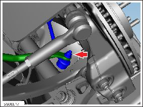
- Remove and discard the nuts (x2) that secure the sway bar to the
drop links.
- Release the rubber grommets that secure the front wheel speed sensor harnesses to the body (x4) and the knuckles (x2).
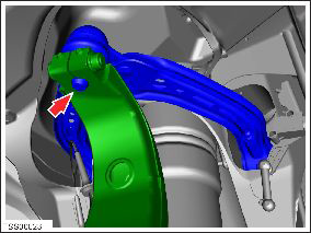
- Remove the nuts that secure the upper control arms to the knuckles, then remove the bolts.
- Release the upper control arms from the knuckles.
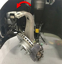
- Tilt the upper sections of the knuckles away from the vehicle.
- Remove the bolts (x4) that secure the sway bar brackets to the subframe.
- Lower the vehicle to provide access to the front trunk area.
- Turn the steering wheel all the way to the right. Use a steering wheel holder or have an assistant hold the steering wheel in this position.
- Slide the sway bar to the RH side of the vehicle as far as it will go, then rotate it down.
- Slide the LH side of the sway bar over the tie rod end. Caution: Do not damage the tie rod ball joint boot.
- Slide the RH side of the sway bar over the tie rod end. Caution: Do not damage the tie rod ball joint boot.
- Release the fir tree clips (x2) from the LH subframe brace.
- Slide the sway bar toward the RH side of the vehicle, until the LH side of the sway bar can be pulled out through the underhood area. Note: Do not attempt to remove the sway bar yet.
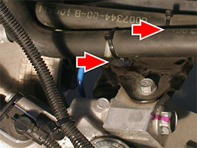
- Release coolant pump 1 from the bracket and pull it toward the
front of the vehicle.
Note: Coolant pump 1 is on the RH side of the vehicle.
Note: The coolant pump assembly includes both the coolant pump and the rubber isolator.
Note: Do not disconnect the coolant hoses from the pump.
.png)
- Remove the sway bar through the underhood area.
Caution: Take care not to damage component(s).
Installation- Insert the RH side of the sway bar through the underhood area.
- Slide the sway bar towards the LH side of the vehicle until the driver's side sway bar bushing is near the A/C line.
- Ensure that the steering wheel is still fully turned to the right.
- Slide the RH side of the sway bar over the tie rod end. Caution: Do not damage the tie rod ball joint boot.
- Slide the LH side of the sway bar over the tie rod end. Caution: Do not damage the tie rod ball joint boot.
- Move the sway bar into its standard position.
- Remove the steering wheel holder, if applicable. Turn the steering wheel to the center position.
- Raise the vehicle.
- Install the bolts (x4) that secure the sway bar brackets to the subframe (torque 23 Nm).
- Install the nuts and bolts that secure the upper control arms to the knuckles (torque 60 Nm).
- Secure the rubber grommets that secure the wheel speed sensor harnesses to the body (x4) and the knuckles (x2).
- Install new nuts (x2) that secure the sway bar to the drop links
(torque 70 Nm).
- Reinstall all components that were removed for access.
Caution: Replace all nylon-insert locknuts.
Caution: Only fully tighten suspension nuts and bolts when the vehicle is on a 4-post lift and the suspension is in the ride height position.
READ NEXT:
 Sway Bar - Front (Dual Motor) (Remove and Replace)
Warning: If the vehicle has air suspension, activate "Jack"
mode on the touchscreen before raising and supporting the vehicle.
Warning: If the 12V power supply is disconnected, do
not att
Control Arm - Upper - Front - LH (Remove and Replace)
Warning: If the vehicle has air suspension, activate "Jack"
mode on the touchscreen before raising and supporting the vehicle.
Removal
Position the vehicle in preparation for raising
Control Arm - Upper - Front - RH (Remove and Replace)
Warning: If the vehicle has air suspension,
activate "Jack" mode on the touchscreen before raising and
supporting the vehicle.
Note: Graphics show the LH side. The RH side is similar.
SEE MORE:
Charging stopped due to large voltage drop
Remove extension cords / Have wiring inspected
Charging has been interrupted because the onboard charger in your vehicle has
detected an unusually large voltage
drop.
Likely causes of this issue include:
Problems with the building wiring and/or the wall outlet.
An extension cord or other wirin
Handle and Cable Assembly - 80A Wall Connector (Remove and Replace)
Note: This procedure describes how to remove and replace
the 80A Wall Connector handle and cable assembly. For instructions
on how to remove and replace the 40A Wall Connector handle and cable
assembly, refer to procedure 50024002 (refer to procedure).
Removal
Warning
