Tesla Model S: HV Junction Box - Cover - 2nd Generation (Remove and Replace) - Removal
Warning: Only technicians who have been trained in High Voltage Awareness are permitted to perform this procedure. Proper personal protective equipment (PPE) and insulating HV gloves with a minimum rating of class 00 (500V) must be worn any time a high voltage cable is handled. Refer to Tech Note TN-15-92-003, "High Voltage Awareness Care Points" for additional safety information.
Removal
- Disconnect 12V and HV power:
- Rear wheel drive (RWD): Refer to procedure.
- Dual Motor: Refer to procedure.
- Remove the 2nd row seat frame:
- Standard seats: Refer to procedure.
- Executive seats: Refer to procedure.
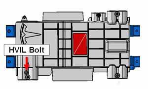
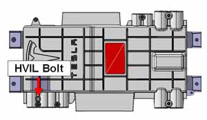
- Remove the HVIL bolt from the HVJB cover. Do not remove the
remaining fasteners at this time.
- North America, Japan (torque 4 Nm)
Note: In North American and Japanese vehicles, the HVIL bolt is one-time use only. Install a new bolt during reinstallation.
- Europe, APAC (torque 5 Nm)
Note: In European and APAC vehicles, the HVIL bolt can be reused during reinstallation.
- North America, Japan (torque 4 Nm)
Warning: Ensure that the multimeter and leads are capable of handling at least 500V.
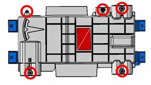
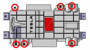
- Remove the remaining fasteners that secure the HVJB cover.
- North America, Japan (torque 8 Nm)
Note: In North American and Japanese vehicles, there are 5 additional fasteners.
- Europe, APAC (torque 8 Nm)
Note: In European and APAC vehicles, there are 6 additional fasteners.
- North America, Japan (torque 8 Nm)
- Use a multimeter to check voltages across the HV cables and to
ground:
Warning: If any voltage reading is more than 10V, the high voltage contactors are not fully opened. Due to the risk of electrocution, contact Service Engineering before performing any further work.
Warning: Never use a fastener or an e-coated surface as a path to ground. In this procedure, ensure that the ground strap from the HVJB is secure to the body and use the lug as a path to ground.
- The 4 HV cables to the HV battery and rear drive unit
- The 2 HV cables to the forward junction box
- The 2 HV cables to the charge port
- Dual Motor vehicles only: The 2 HV cables to the front drive unit
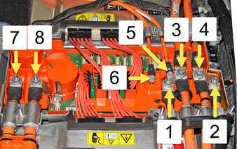
Note: Vehicles with 3-phase charging have 4 harnesses to the charge port:1 B+ Front Drive Unit (if equipped) 2 B- Front Drive Unit (if equipped) 3 B+ battery/drive inverter 4 B- battery/drive inverter 5 B+ DCDC converter 6 B- DCDC converter 7 B- charge port 8 B+ charge port 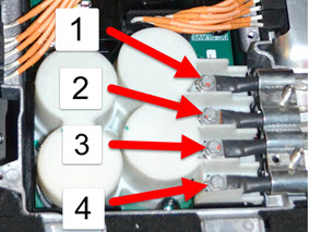
1 B+ N charge port 2 B- L1 charge port 3 B+ L3 charge port 4 B- L2 charge port
READ NEXT:
 North America and Japan only: Inspect the shield collar clamp
Insert the HVIL bolt into the shield collar clamp by 2 threads.
1
Install HVIL bolt 2
threads
HV Junction Box - Cover - 2nd Generation (Remove and Replace) -
Installation
Installation
Position the HVJB cover.
Install the HVIL bolt loosely. Do not tighten it fully at this
time.
North America, Japan
Note: In North American a
HV Junction Box - Reed Switch - 1st Generation (Remove and Replace)
Note: This procedure only applies to vehicles with the
1st generation High Voltage Junction Box.
Special tools required for this procedure:
Supplier
SEE MORE:
Striker - Liftgate (Remove and Replace)
Removal
Open liftgate.
Remove liftgate striker cover.
Remove bolts (x2) securing striker to body (torque 10 Nm).
Remove striker from vehicle.
Assembly - Top Pad - Instrument Panel (Remove and Install)
Warning: If the 12V power supply is disconnected, do
not attempt to open any doors with door glass in closed position.
Failure to follow this instruction could result in door glass
shatter.
Note: Before disconnecting the 12V power supply,
ensure that the driver's door window
